5.1 Verifiable Read Head Types
The following read head types can be verified using the AMS Service Tool:
| Read Head Type | Applicable Range |
|---|---|
| AMSA 3B / 4B | From serial number 150000 |
| AMSABS 3B / 4B | From serial number 161929 |
| AMSABS DC | All read heads |
5.2 Required Tools
- 220V / 120V power supply
- Laptop / Personal computer
- AMS Konfig V2.3 software (see Chapter 4 for installation)
- Read head interface connector
- AMS Service Tool
5.3 Adapter Cable
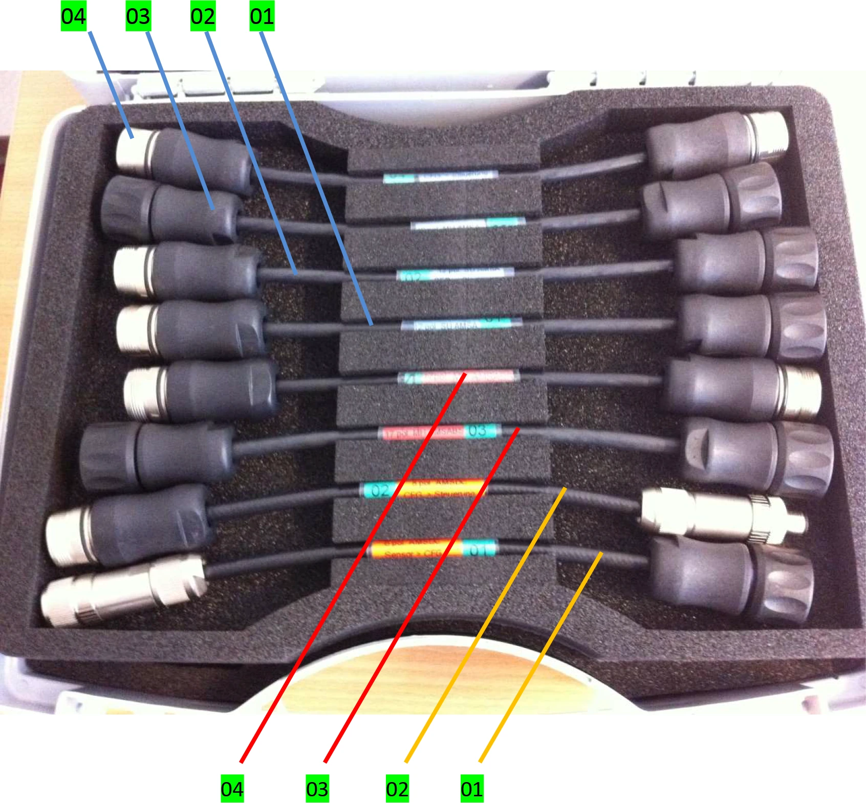
| Read Head Type | Adapter Cable Color | Encoder Side | No. | No. | CNC Side |
|---|---|---|---|---|---|
| AMSA | Blue adapter cable | 12pole SU AMSA <Sensor CFG.> 823 001 187 | 01 | 02 | 12pole SU AMSA <CFG. Control> 823 001 188 |
| 12pole MU AMSA <Sensor CFG.> 823 001 189 | 03 | 04 | 12pole MU AMSA <CFG. Control> 823 001 190 | ||
| AMSABS | Red adapter cable (No adapter cable needed for SH connector) | 17pol. MH AMSABS <Sensor CFG.> 823 001 197 | 03 | 04 | 17pol. MH AMSABS <CFG. Control> 823 001 198 |
| AMSABS DC | Orange adapter cable | 8pol. AMSABS DC <Sensor CFG.> 823 002 755 | 01 | 02 | 8pol. AMSABS DC <CFG. Control> 823 002 756 |
5.4 Additional Equipment
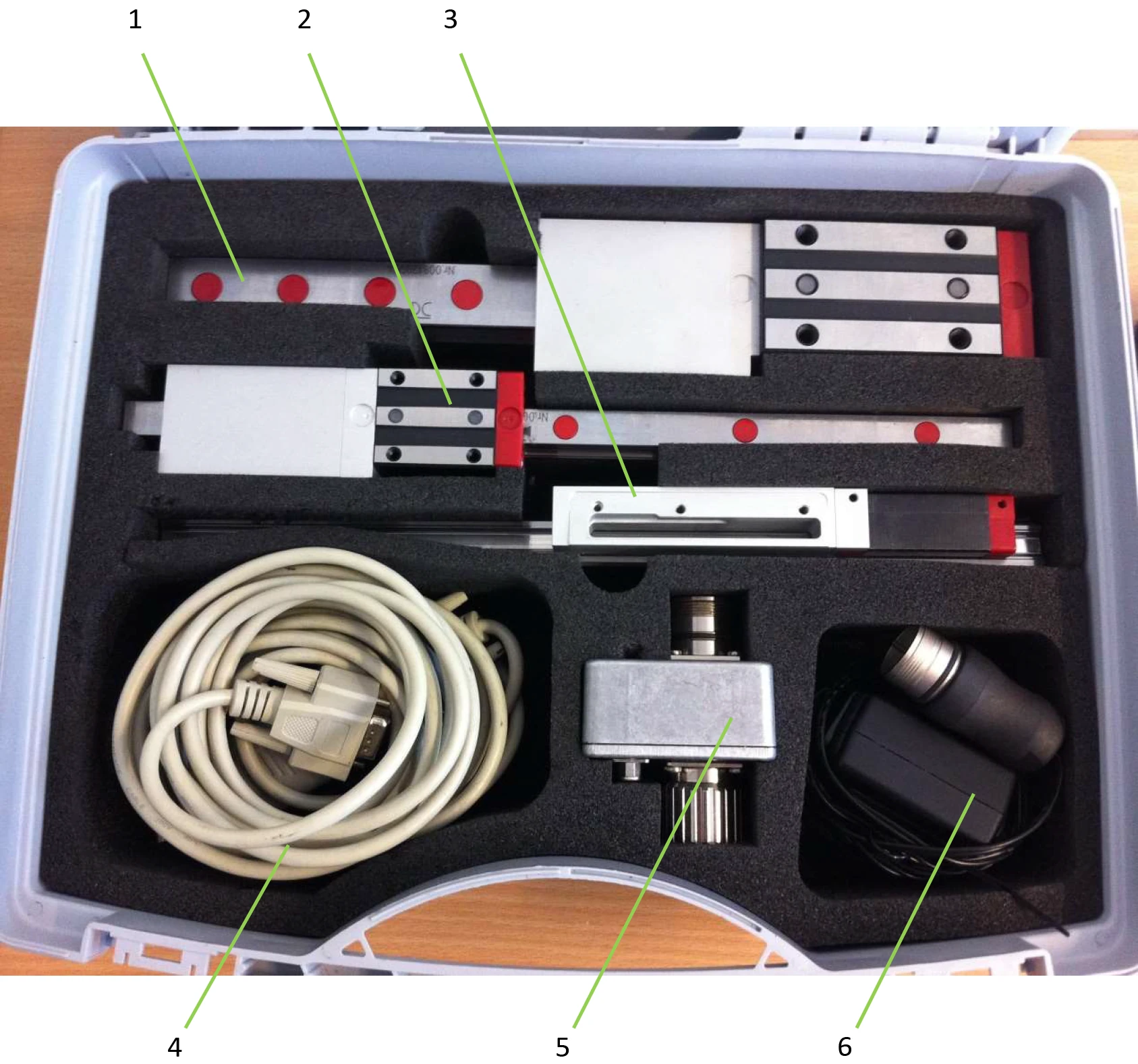
| No. | Equipment Name |
|---|---|
| 1 | AMSA 3B test guide rail |
| 2 | AMSA 4B test guide rail |
| 3 | AMSABS 3B & 4B test guide rail |
| 4 | Data transfer cable (with Lindy adapter and USB connector) |
| 5 | Communication box |
| 6 | External power cable (220V, country adapter not included) |
5.5 Connecting Components
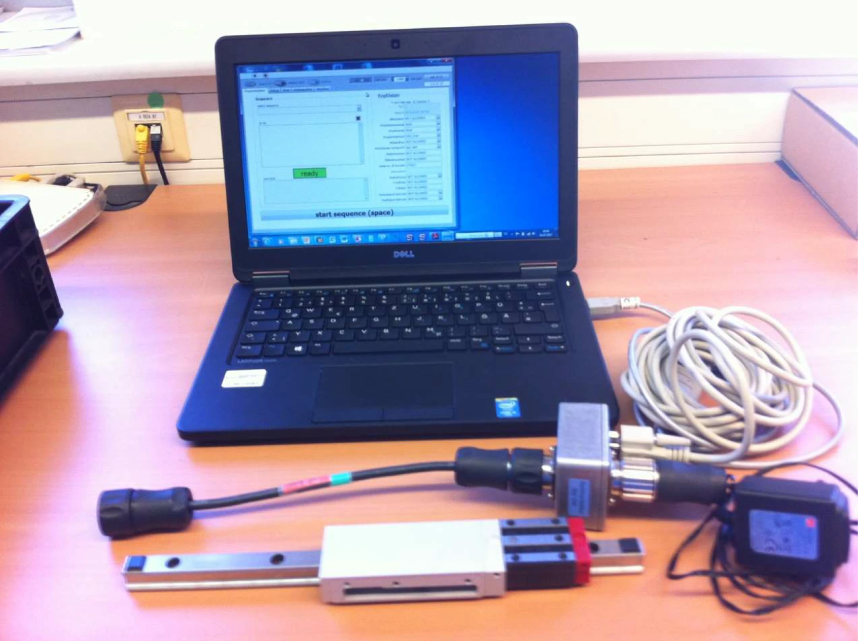
- Connect the data transfer cable (1) to the laptop via USB port, and the other end to the communication box (5)
- Select the adapter cable (01/03) according to the overview table, and connect it to the encoder side of the communication box (5)
- Connect the service tool to the read head interface via the adapter cable (01/03)
- Verify all connections are properly secured
5.5.1 Connection with External Power Supply
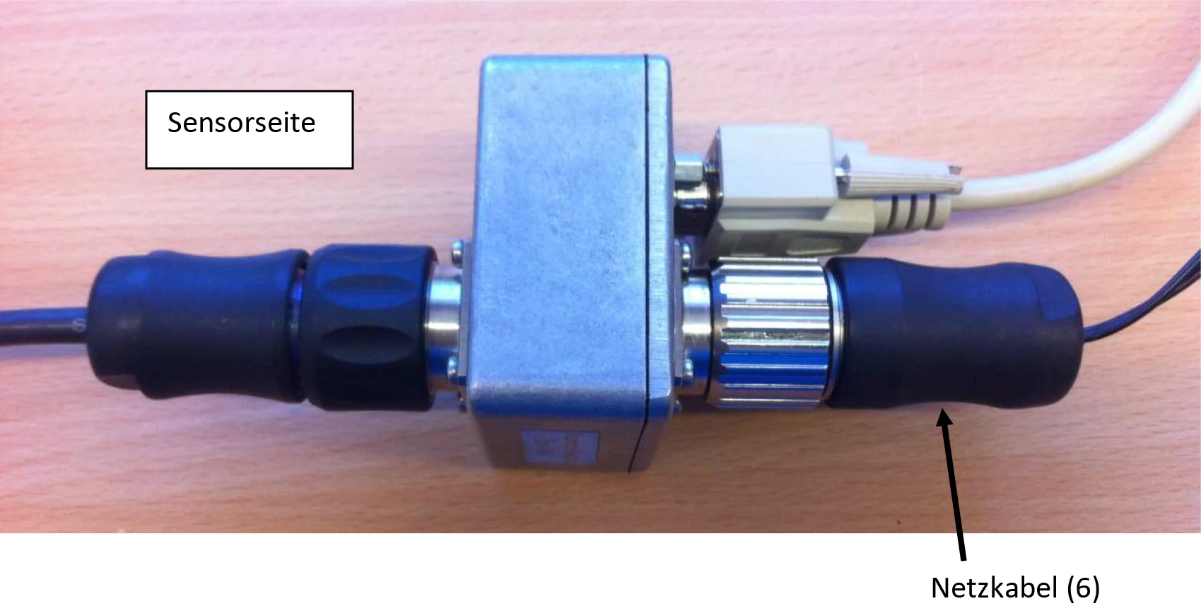
The power cable (6) is connected to the encoder side.
5.5.2 Connection with Controller
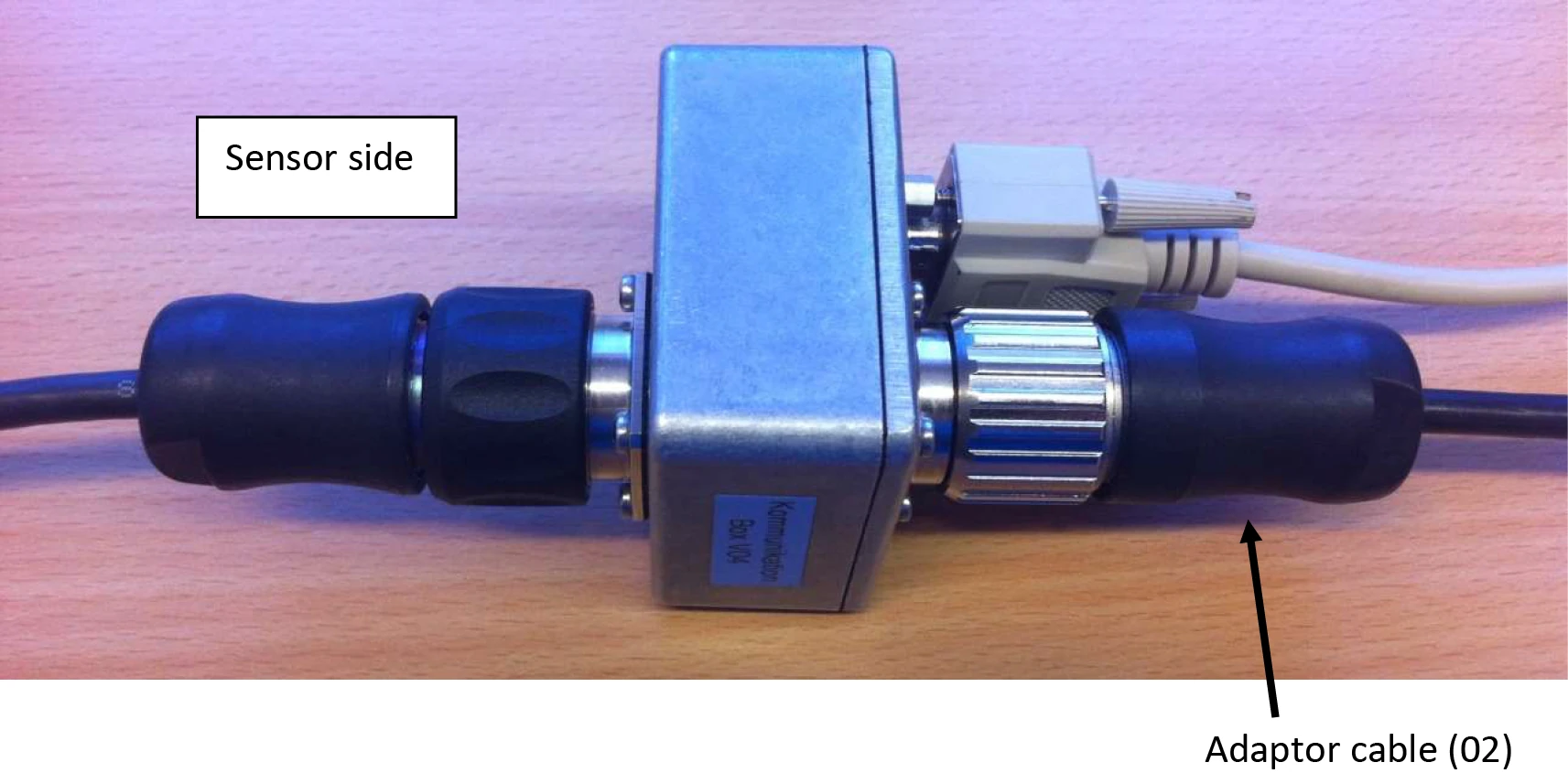
The adapter cable (02) is connected to the encoder side.