Chapter 7 Post-Installation
Post-Installation
7.1 Checking Parallelism and Running Accuracy
After installation, check the function and accuracy of the guide rail as follows:
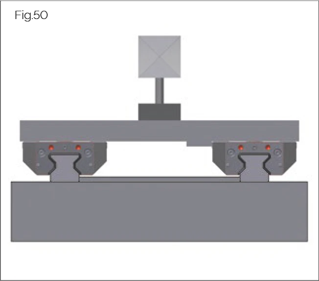
Parallelism
Check compliance with the parallelism tolerance using a dial indicator and two connected carriages.
Use the vertical lateral locating surface on the parallel guide rail as the reference surface. A special adapter plate can be used when checking AMS guide rails.
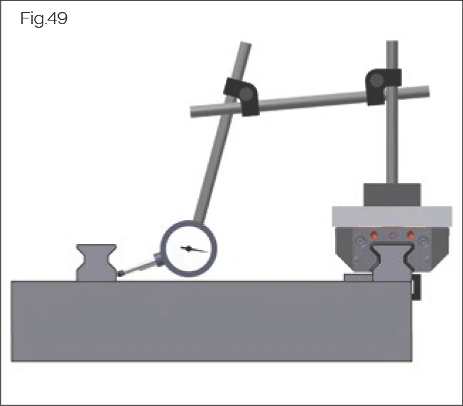
Running Accuracy
Check running accuracy using a laser, autocollimator or dial indicator. For correct results, measurements should always be taken on the machine slide, not on individual carriages.
Vertical Running Measurement with Two Measuring Sensors
It is recommended to use two measuring sensors to identify angular deviations of the carriage along the longitudinal guide rail axis by differential measurement. When using a laterally positioned measuring sensor, ensure it is as close as possible to the guide rail.
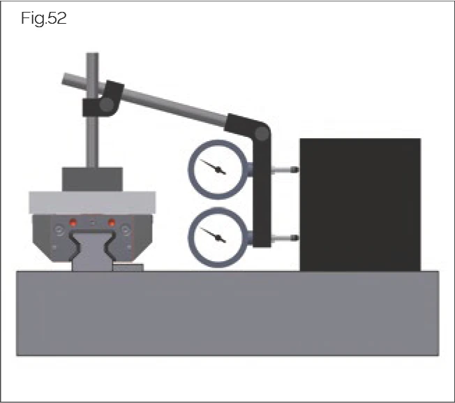
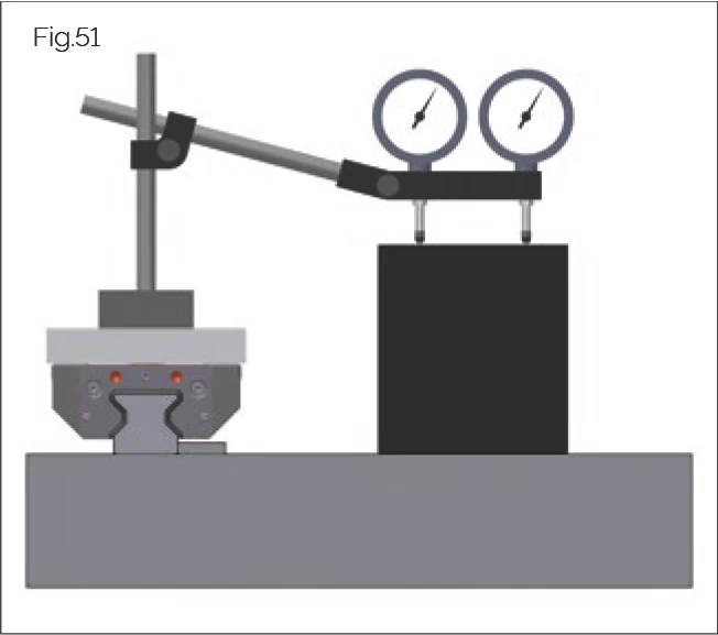
Horizontal Running Measurement with Two Measuring Probes
It is recommended to use two measuring sensors to identify angular deviations of the carriage along the longitudinal guide rail axis by differential measurement. When using a deep-positioned measuring probe, ensure it is as close as possible to the center of the guide rail.
7.2 Installing Screw Covers
CAUTION!
Risk of personal injury from sharp edges!
May result in cuts.
- Wear gloves.
- Protect seals with an assembly protection strip when the carriage passes over unsealed guide rail fixing holes.
The following screw covers are available:
- MRK plastic plugs — for MR roller guideways
- BRK plastic plugs — for BM ball guideways
- MRS brass plugs — for MR roller guideways
- BRS brass plugs — for BM ball guideways
- MRZ stainless steel plugs — for MR roller guideways
7.2.1 MRK/BRK Plastic Plugs
This section describes the installation of MRK plastic plugs to cover fixing holes on MONORAIL MR guide rails, and BRK on MONORAIL BM guide rails.
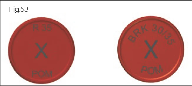
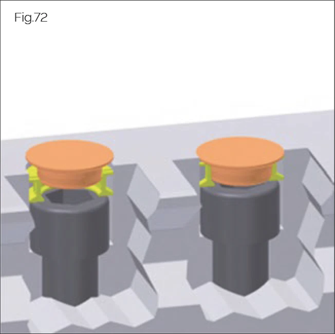
Identification
The marking on the back of the plastic plugs can be used to identify whether they are MRK plastic plugs for MONORAIL MR (right in figure) or BRK plastic plugs for MONORAIL BM (left in figure).
Plastic plug dimensions see "Appendix" on page 72.
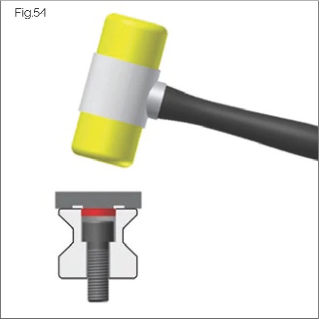
Required Tools
Use a plastic mallet and pad (such as a Perspex block or assembly rail) for installation.
Assembly Procedure
- Clean the guide rail fixing holes.
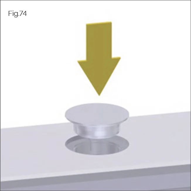
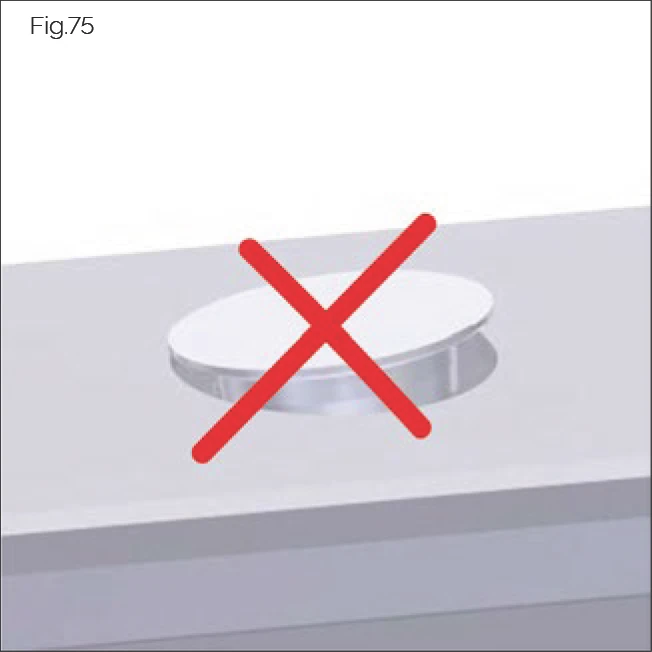
- Place the plug in the guide rail fixing hole. Ensure the plug is placed parallel to the guide rail surface.
- Gently hammer the plug.
- Check that they are correctly seated.
- Remove any debris.
- Hammer the plugs until flush with the surface.
Plastic Plugs Installation Video Tutorial
Plastic Plugs MRK/BRK Installation
Installation method for rail fixing hole plastic plugs. MRK for MONORAIL MR series, BRK for MONORAIL BM series, preventing debris from entering screw holes. | Duration: ~1 min
7.2.2 MRS/BRS Brass Plugs
CAUTION!
Risk of personal injury from sharp-edged guide rail fixing holes and sheared or flying brass fragments!
May result in cuts.
- Wear gloves.
- Wear safety goggles when using compressed air.
CAUTION!
Risk of personal injury from not following manufacturer's instructions!
Hydraulic components may be damaged and malfunction, resulting in injury.
- Follow the manufacturer's installation, operation and maintenance instructions.
This section describes the installation of MRS plugs on MONORAIL MR guide rails, and BRS brass plugs on MONORAIL BM guide rails, using the MWH or BWH hydraulic assembly tool and MZH hydraulic cylinder.

Identification
MRS and BRS brass plugs typically have different structures. The following shows the geometric characteristics of the different plugs that can be used to identify brass plugs.
MRS brass plugs have a tapered outer contour (1). The top surface (2) of the plug has an annular recess.
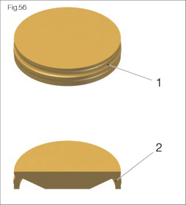
BRS brass plugs have an annular groove (1). The underside of the brass plug has a groove (2).
BRS plugs require special BM guide rails with non-chamfered mounting holes.
Hydraulic Unit
Recommended performance specifications:
- Nominal working pressure 200 to max. 350 bar
- Capacity > 5.8 l/min @ 190 bar
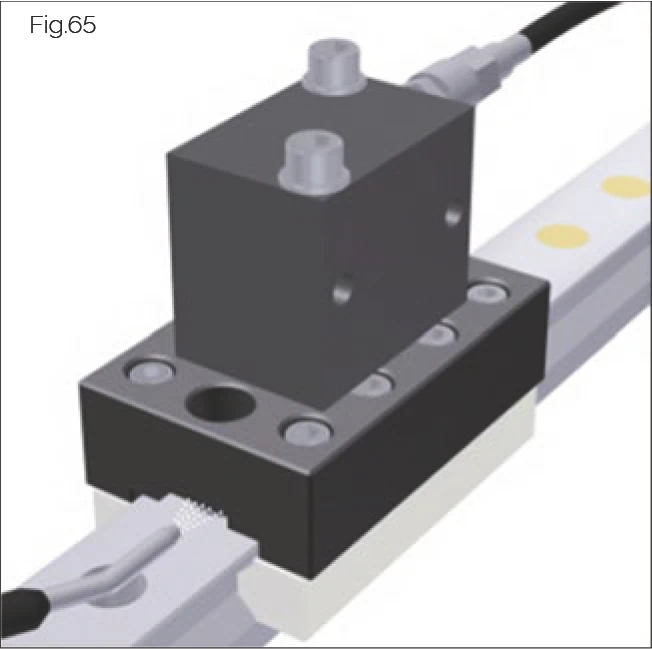
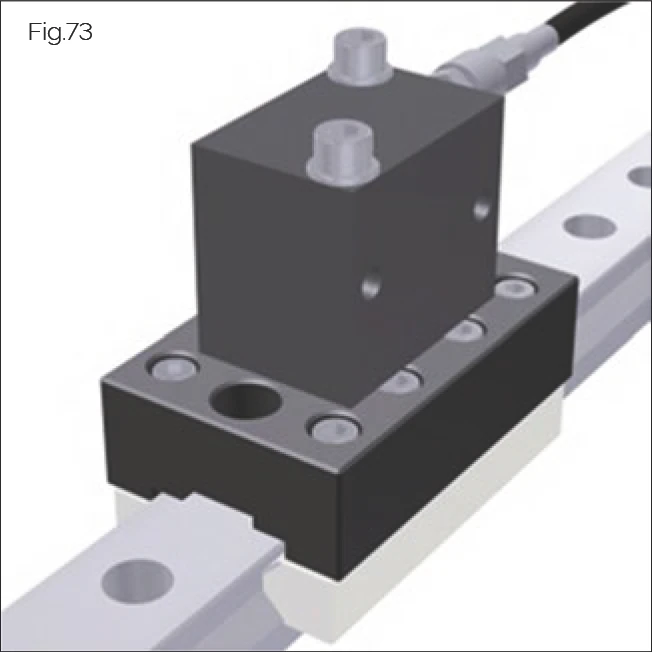
MWH/BWH* Assembly Tool
SCHNEEBERGER recommends using the MWH/BWH hydraulic assembly tool for correct installation of brass plugs. The tool consists of a size-dependent sliding shoe and MWH/BWH pressing punch, as well as a universal MZH hydraulic cylinder, which must be ordered separately. The hydraulic cylinder is a simple-acting block cylinder with spring return. The required quick coupling is not included in the delivery.
Although the MWH/BWH assembly tool is maintenance-free in principle, the pressing punch may show signs of wear after prolonged use. This may affect the achievable positional tolerance of the plugs and result in exceeding permissible values. Therefore, the pressing punch must be checked regularly and replaced if necessary. Punches are available from SCHNEEBERGER as replacement parts.
For the MZH hydraulic cylinder, the maintenance procedures specified in the manufacturer's operating instructions should be followed.
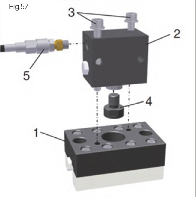
Assembly:
- Screw the pressing punch (4) into the hydraulic cylinder (2) by hand until it stops and tighten lightly.
- Connect the MZH hydraulic cylinder (2) and sliding shoe (1) using the supplied screws (3).
- Connect the hydraulic unit to the 1/4" hydraulic thread of the hydraulic cylinder using the quick coupling (5).
- Assembly tool dimensions see "Accessory Dimensions" on page 71.
Assembly Process
- Mount the MWH/BWH assembly tool on the guide rail. It is recommended to use the MRM/BRM assembly rail for this purpose.
*MWH is shown. The sliding shoe for BWH is different.
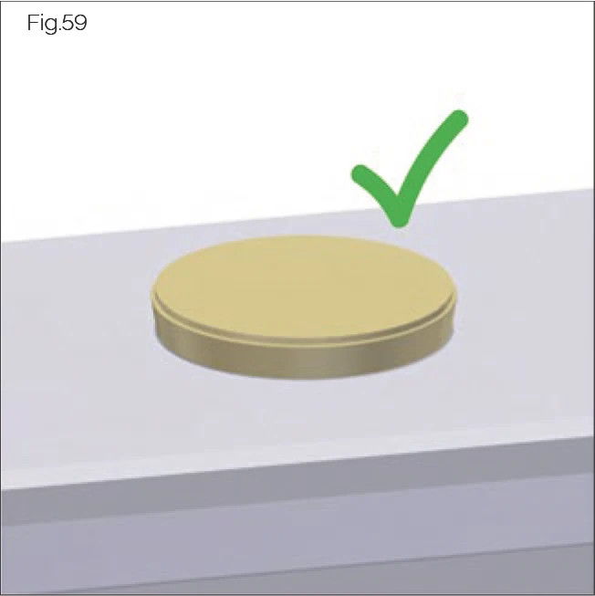
- Insert MRS brass plugs (tapered) with the smaller diameter end facing down. Insert BRS brass plugs with the grooved side facing down.
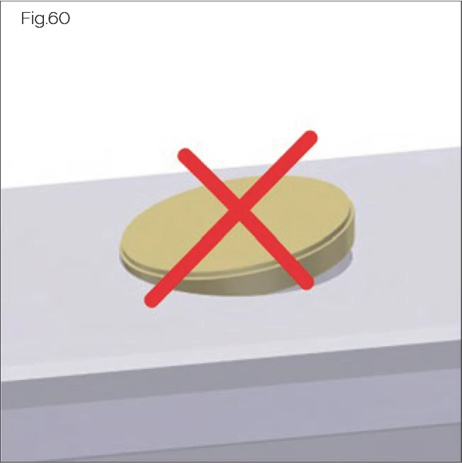
Ensure the plug is placed parallel to the top surface in the fixing hole.
- Slide the assembly tool over the plug and position it centrally.
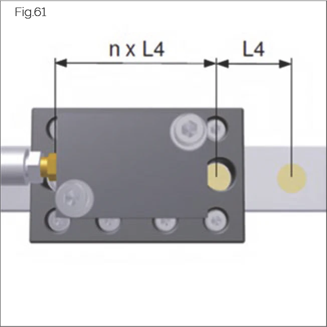
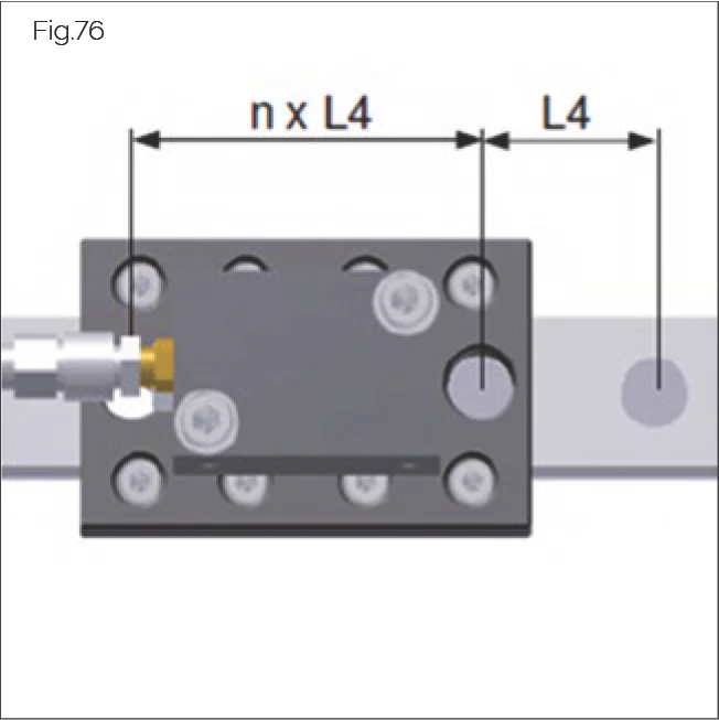
- Slide the assembly tool until the two outer control holes or recesses are directly above the guide rail fixing hole. (Depending on size, the control holes are one or two L4 hole pitches from the installation position.)
→ The pressing position has been reached.
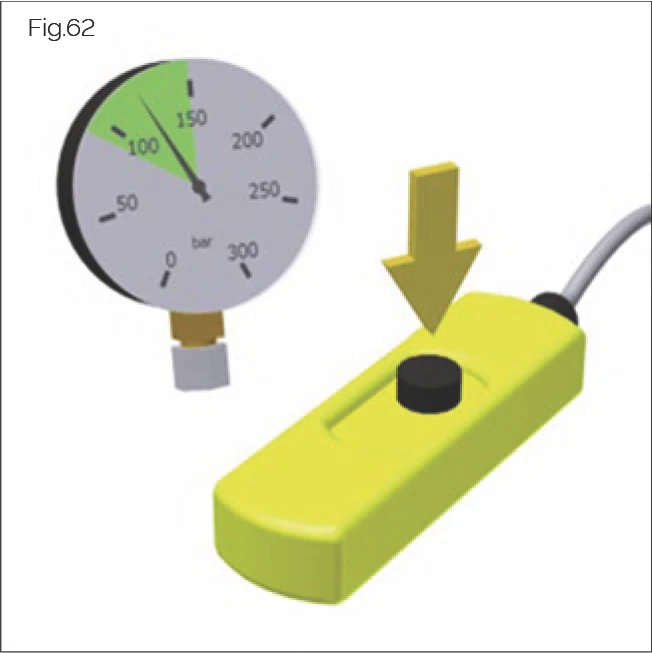
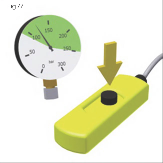
- Switch on the hydraulic unit and set the required pressure using the pressure control valve.
Recommended pressure:
- MRS: 80 to 120 bar (250 bar for MR 100)
- BRS: 80 to 120 bar
Note: The required pressing pressure depends on size and manufacturing tolerances. Higher pressures may be required in individual cases.
ATTENTION!
Risk of material damage from exceeding permissible operating pressure!
Plugs/tools may be damaged.
- Never exceed the permissible operating pressure of 350 bar for the hydraulic cylinder.
- Briefly operate the one-hand control panel to activate the hydraulic cylinder.
→ You will hear a crisp clicking sound.
- Immediately release the power switch of the hydraulic cylinder.
→ The hydraulic cylinder will return to its initial position.
- Slide the assembly tool to one side.
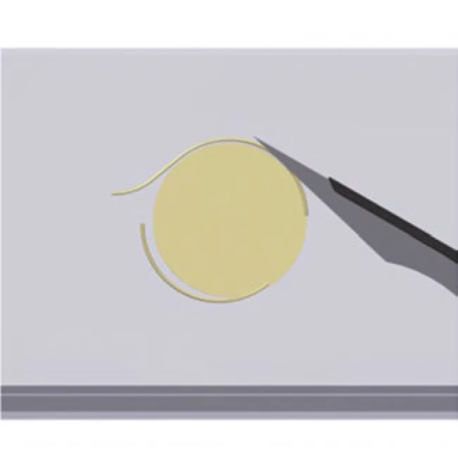
→ The plug is pre-pressed in, protruding approximately 0.2 - 0.3 mm above the guide rail surface.
- Remove debris generated during pressing, or clear it using a suitable tool (scalpel, sharp blade, etc.). Ensure the plug and guide rail are not scratched.
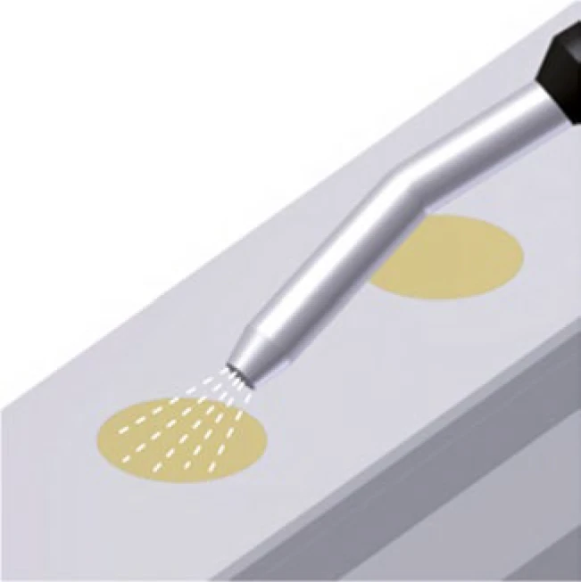
- Use compressed air to blow loose debris from the guide rail surface. Use a brass brush to remove residual debris if necessary. Check that all debris has been removed.
- Blow debris from the gap between the sliding shoe and the top surface of the guide rail with compressed air to remove debris adhering to the pressing punch.
- Slide the assembly tool over the plug being pressed again and position it. Repeat the pressing process.
→ The plug is fully pressed in and is now flush with the guide rail surface.
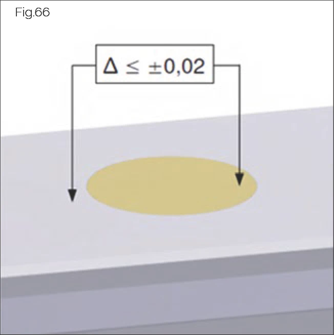
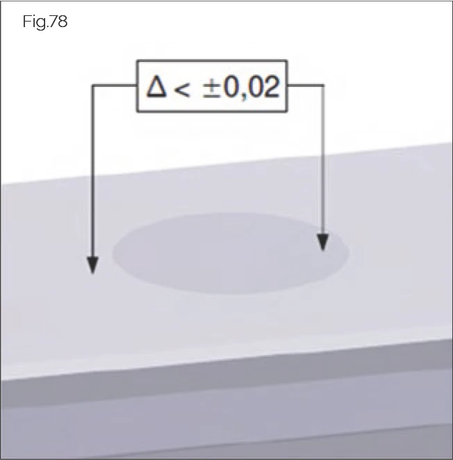
- Check that the height difference between the guide rail and the top surface of the plug is permissible (measured at the plug or fixing hole edge as +/- 0.02 mm).
- If necessary, repeat the pressing process with higher pressure until the correct position is achieved.
- Ensure no residual debris or burrs remain. If necessary, use a polishing sponge to finish the plug and guide rail surface.
- Ensure the plug is correctly positioned.
Disassembly
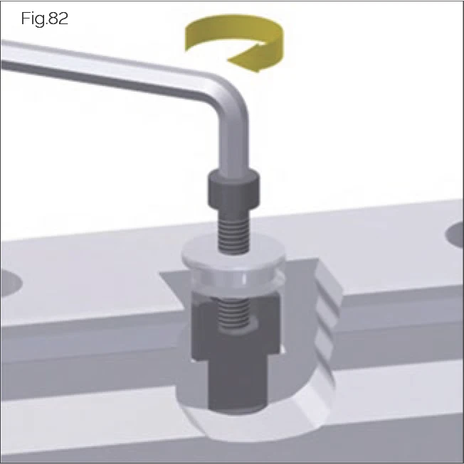
Once correctly installed, the brass plugs are very firmly seated in the guide rail fixing holes. We therefore recommend using a suitable extraction device for disassembly. Standard socket head cap screws are suitable for this purpose. Recommended screws and core hole diameters see "Screw Tightening Torques" on page 75.
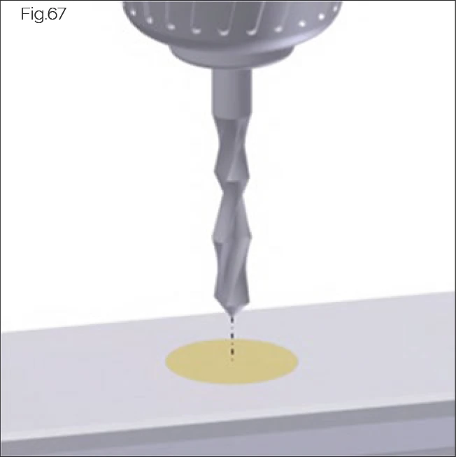
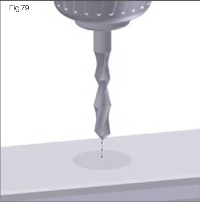
- Make a punch mark in the center of the plug, then drill through the plug at this point using a hand drill. Be careful not to damage the guide rail fastening screw. The drill diameter should be selected according to the socket head cap screw being used.
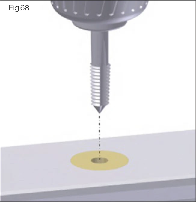
- Use a tap to cut a thread in the plug. Remove debris from the thread.
- Screw the socket head cap screw into the plug by hand until the tip of the screw contacts the head of the guide rail fastening screw.
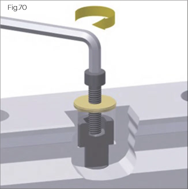
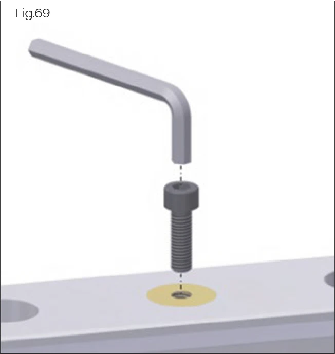
- Tighten the screw using a suitable Allen key.
→ The plug will be pushed upward (see figure).
- Continue tightening the screw until the plug is fully extracted.
- Remove the plug by hand.
- Check the guide rail fixing hole and fastening screw for damage. If necessary, use a grinding tool to finish the fixing hole and replace the fastening screw.
Metal Plugs Installation Video Tutorial
Metal Plugs MRS/MRZ Installation
Installation method for rail fixing hole metal plugs. MRS is brass, MRZ is steel, suitable for environments requiring higher protection levels or chemical resistance. | Duration: ~4 min
7.2.3 MRZ Steel Plugs
CAUTION!
Risk of personal injury posed by sharp edges!
Could result in cutting injuries.
- Wear gloves.
- Protect wipers on carriages with an assembly protection strip when passing the carriage over unsealed rail fixing holes.
CAUTION!
Risk of personal injury posed by non-compliance with manufacturer's guidelines!
Hydraulic components can become damaged and malfunction, resulting in injury.
- Follow the manufacturer's instructions for installation, operation and maintenance.
This section describes the installation of MRZ steel plugs for the covering of rail fixing holes on MONORAIL MR guide rails using the MWH hydraulic assembly tool.
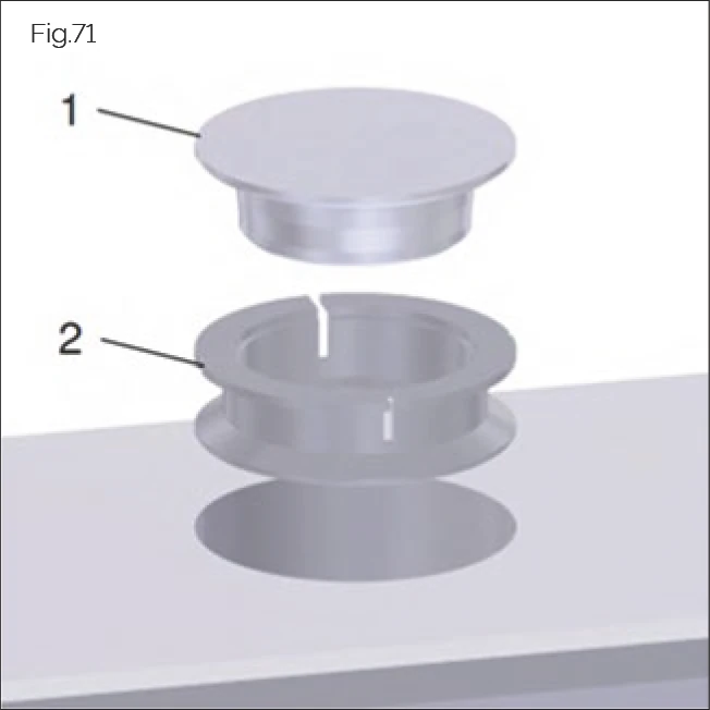
Functional Principle
Two-part MRZ steel plugs made from non-rusting stainless steel consist of the actual plug (1) and a clamping ring (2). This has two ring-shaped flanges and an upper surface featuring multiple slots. During assembly, the clamping ring is laid loose onto the screw head in the guide rail fixing hole. The slightly conical plug has a plate-shaped upper surface with a diameter that corresponds approximately to that of the guide rail fixing hole.
Pressing the plug into the clamping ring causes the latter to expand slightly, applying the ring to the wall of the fixing hole and creating a locking force between the fixing hole and the plug. This functional principle ensures a very firm and secure grip and sealing of the guide rail fixing hole, as well as a flush positioning of the plug in relation to the guide rail surface for the optimal functioning of carriage wipers.
Required Tool
MWH Installation Tool
For a description of the MWH assembly tool and its assembly, see "MRS/BRS brass plugs" on page 34.
Assembly Process
- Slide the MWH assembly tool onto the guide rail. Recommendation: Use an MRM assembly rail for this purpose.
- Lay the clamping ring inside the guide rail fixing hole with the slitted surface facing upward.
- Lay the plug onto the ring with the conical side facing downward.
Ensure that the plugs sit plane-parallel to the rail surface in the fixing holes.
NOTE: The clamping ring has a small recess on the inside of its upper portion that enables the plug to align with it under light pressure.
- Slide the assembly tool over the plug and position it centrally.
- Slide the assembly tool until both external control holes or recesses in the tool (MWH 25 - 100) are positioned exactly over a guide rail fixing hole. (Depending on the size, the control holes are one or two L4 hole spacings from the installation position.)
→ The stamping position has been reached.
NOTE: In order to install the plugs at the extreme end of the rail, the assembly tool can be slid beyond the rail end.
- Switch on the hydraulic unit and set the desired pressure using the pressure control valve.
Recommended pressure: 100 to 200 bar
NOTE: The stamping pressure required is dependent on the size and manufacturing tolerances. Individual cases may require that a higher pressure up to approx. 250 bar is used.
ATTENTION!
Risk of material damage posed by exceeding the permissible operating pressure!
Plugs/tool may be destroyed.
- Under no circumstances exceed the hydraulic cylinder's permissible operating pressure of 350 bar.
- Briefly operate the one-handed control panel to activate the MZH hydraulic cylinder.
→ You will hear a clear clicking sound.
- Immediately release the hydraulic cylinder's power switch.
→ The hydraulic cylinder will return to its initial position.
- Slide the assembly tool to one side.
→ The plug has been fully pressed in and is now flush with the guide rail surface.
- Ensure that the plug is positioned correctly:
- Check that any height difference between the rail and the upper surface of the plug is permissible (+/- 0.02 mm measured at the edge of the plug or fixing hole).
- If necessary, repeat the pressing procedure with a higher pressure until the correct position has been achieved.
ATTENTION!
Risk of material damage posed by use of incorrect screws!
Cross wipers/carriages may become damaged.
- Safe functionality of the steel plugs is only guaranteed with the use of DIN 912/ISO 4762 high-headed screws to fasten the guide rails.
- Any markings on the screw-head must not be raised.
Disassembly
Once properly installed, the steel plugs are fixed into the guide rail fixing holes very firmly. We therefore recommend that disassembly is carried out using an appropriate extracting device. A standard Allen screw is suitable for this purpose. For recommended screw and core hole diameters, see Table "Dimensions of MRZ steel plugs" on page 72.
- Make a punch mark in the centre of the plug and then drill through the plug at this point using a portable drill. Take care not to damage the guide rail fastening screw. The drill diameter should be selected in accordance with the Allen screw used.
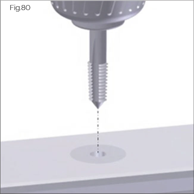
- Use a thread cutter to cut a thread into the plug. Remove any swarf from the thread.
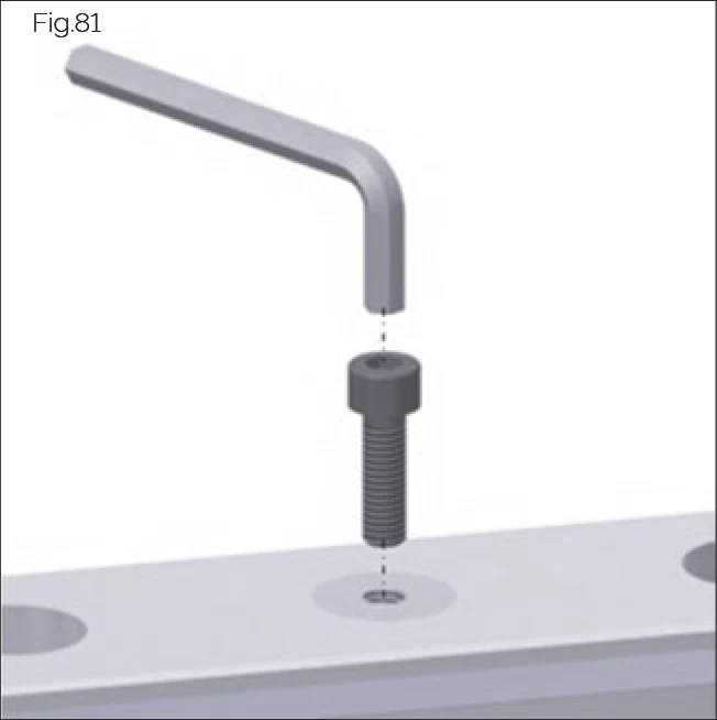
- Screw the Allen screw into the plug by hand until the tip of the screw comes into contact with the head of the guide rail fastening screw.
- Tighten the screw using a suitable Allen wrench.
→ The plug together with the clamping ring will be forced upwards (see figure).
- Continue tightening the screw until the plug is fully extracted.
- Remove the plug by hand.
- Check the guide rail fixing hole and fastening screw for damage. If necessary, finish the fixing hole with a grinding tool and replace the fastening screw.
7.2.4 MAC/BAC Cover Strips
This section describes the installation of the MAC/BAC cover strip for MONORAIL MR and BAC cover strip for MONORAIL BM to cover the mounting holes, using the MWC assembly tool for MR and the BWC assembly tool for BM.
CAUTION!
Risk of personal injury posed by cover strip edges and ends!
Could result in cutting injuries.
- Wear gloves.
ATTENTION!
Risk of material damage posed by bent cover strips!
Cover strips can become bent during storage and transportation, which may cause damage to carriage wipers.
- Always ensure that cover strips are supported along their full length.
- Do not use bent cover strips.
Identification
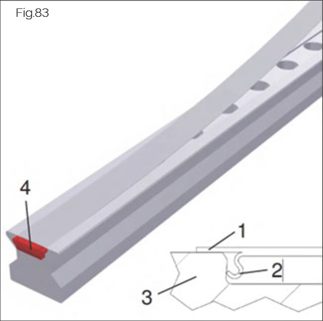
The MAC cover band made from stainless spring steel consists of a smooth steel strip (1) with S-shaped spring elements on the underside (2) for fastening. Installation is carried out on special cover strip rails (3) with a dovetail groove. Once installed, the cover strip lies flat with a slight curvature on top of the guide rail covering its upper surface in the area where the guide rail fixing holes are located. The edges of the guide rail upper surface are left uncovered. The strip is held in place by the S-shaped spring elements, which hook into the guide rail groove and guarantee a firm and secure grip thanks to the resulting locking fit. The strip is also secured at its ends by special end pieces (4) which prevent the retaining elements from springing back and the cover strip from lifting. The end pieces simultaneously seal the frontal gap between the guide rail and cover strip.
- Steel strip
- S-shaped spring elements
- Dovetail groove rails
- End pieces
Required Tool
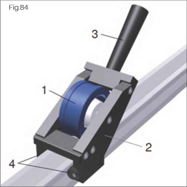
MWC/BWC assembly tool
- Pressure roller
- Housing
- Handle for manual operation
- Sliders for passing the workpiece along the guide rail
The MWC/BWC assembly tool is maintenance-free. Check the assembly tool regularly and replace it if necessary, as extended use may lead to signs of wear on the sliding components.
The manual MWC assembly tool is recommended by SCHNEEBERGER for proper installation of MAC cover strips and can be obtained from SCHNEEBERGER separately.
Cover Strip Installation Video Tutorial
MAC/BAC Cover Strip Installation
Installation method for rail top dust protection cover strips, effectively preventing chips and dust from entering the rolling area, extending service life. For MONORAIL and AMS series. | Duration: ~3 min
Installation procedure for one-piece strips
Minimum length
- Minimum length for guide rails with cover strip without fixing bracket: L3 ≥ 600 mm
- Where guide rail length < 600 mm, fixing brackets must be used to secure strip ends against lengthwise slippage (see "Completing installation of one-part and multi-part strips" on page 47).
Alignment
- Lay the cover strip loose on the guide rail.
- Adjust the cover strip so that it is positioned centrally.
- Where the standard end pieces are included for securing the strip, the strip will be slightly longer than the guide rail.
- A correctly-aligned strip should have 2 – 3.5 mm of overhang at each rail end.
NOTE: Ensure that this value is observed for proper functioning of the end pieces.
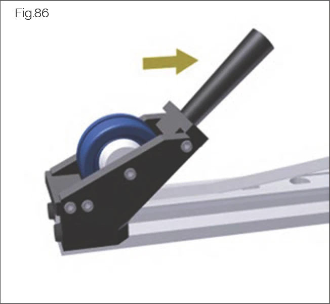
Installation
- Mount the MWC/BWC assembly tool onto one end of the guide rail.
→ Handle will point towards guide rail end.
- Press the strip into the guide rail groove:
- Begin approximately 100 - 200 mm from the guide rail end.
- Simultaneously tilt the tool and move it forwards.
→ The strip will snap audibly into the groove.
NOTE: Do not bend the free strip end at the end of the guide rail. Only move the assembly tool up to the end of the guide rail. Do not move the pressure roller over the end of the guide rail whilst applying pressure.
- Turn the handle of the assembly tool in the direction of installation.
- Slide the assembly tool back over the guide rail.
- Press the strip into the groove along the full length of the guide rail. Move the tool lengthwise whilst tilting it forwards.
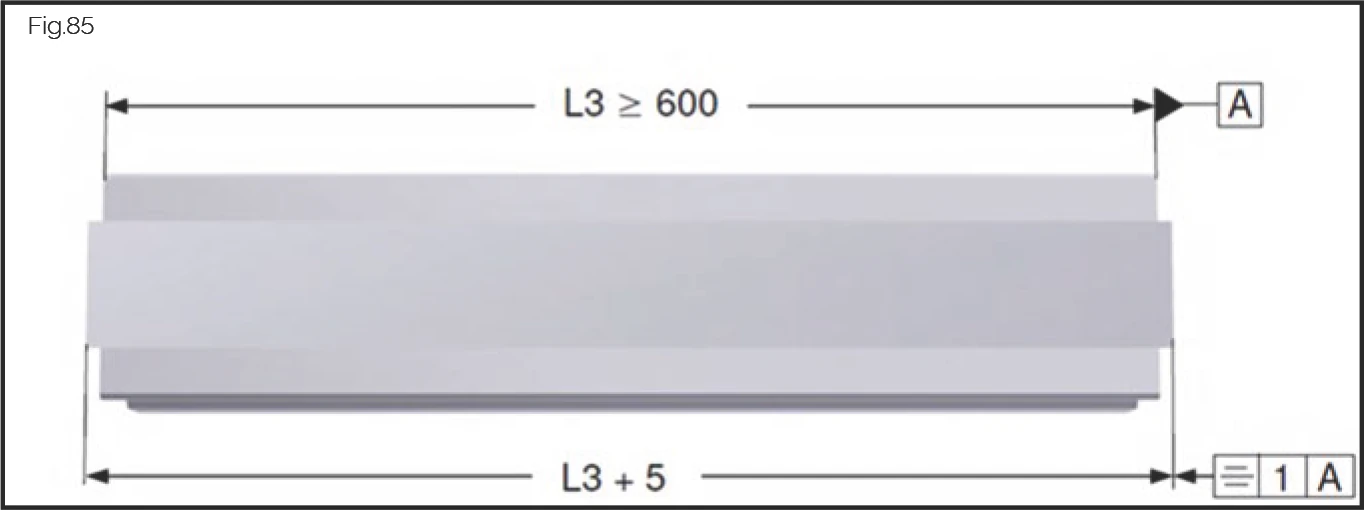
Installation procedure for strips > 6000 mm
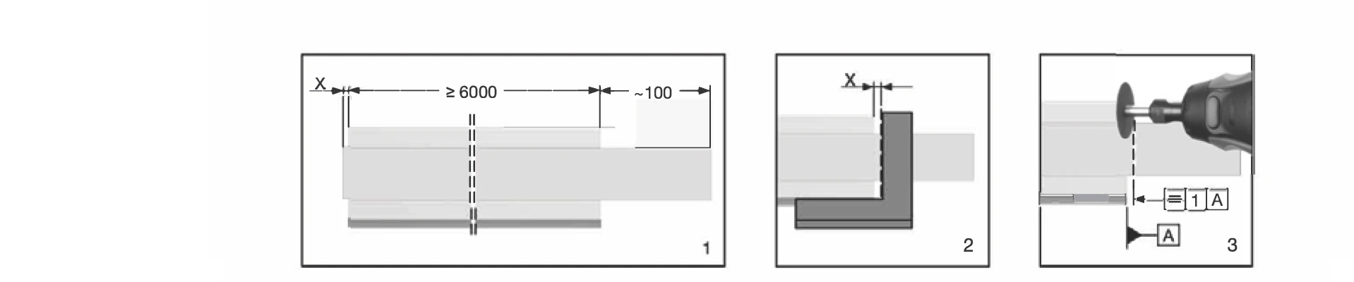
1. Alignment (X = 2-3.5 mm, ≥6000 mm, ~100 mm) 2. Mark cutting position (X = 2.5 ± 0.5 mm) 3. Cut with parting-off grinder
Delivery condition: Cover strips with a length > 6000 mm are delivered oversized and must be cut off on one side by the customer after installation.
Alignment: Before installation, place the cover strip loose on the rail and align so that the strip protrudes X = 2 - 3.5 mm at one end of the rail. This value must be observed to ensure safe functioning of the end pieces for securing the strip. The strip will protrude approx. 100 mm beyond the end of the rail on the opposite side (see Fig.1 above).
Installation: Fit the cover strip over the entire rail length, starting at the rail end with the short overhang, in accordance with the Cover strip MAC/BAC installation instructions.
Cutting off: After installation, cut off the long strip end:
- Mark the cutting edge with the aid of an angle (see Fig.2 above, overhang X = 2.5 ± 0.5 mm).
- Cut off the cover strip square with a parting-off grinder or hacksaw (see Fig.3 above).
- Deburr top and bottom of cut edge, e.g. with an oilstone.
Completing installation: Check that cover strip is correctly located and fit end pieces on both sides in accordance with MAC/BAC installation instructions.
Installation procedure for multi-part strips
General
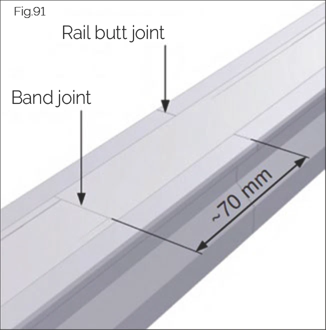
Multi-part strips should only be used if e.g. multi-part guide rails have been laid due to a long axis length and the installation situation requires it. A butt joint always represents a potential problem spot for carriage wipers and should be avoided.
Minimum length
Minimum section length: 600 mm
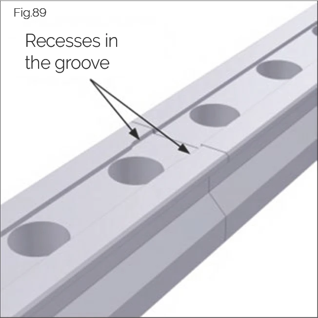
Guide rail installation
Install multi-part guide rails for cover strips in accordance with "Handling guide rails". Install the rail segments so that at each butt joint the groove for the cover strip is continued by the subsequent rail section (see figure).
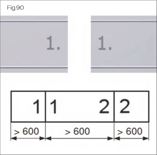
Installation
Multi-part strips should be installed according to the same process used in the case of one-part strips (see "Installation procedure for one-piece strips"). Follow the numbering of the strips. As with multi-part guide rails, the individual strip components are provided with a butt joint number on their underside in the joint area.
In the future, the cover tapes MAC and BAC will be additionally labeled on the protective foil:
- SCHNEEBERGER + type + size
- Arrows for orientation
The arrows must point to the R1 side during both cutting and mounting (regardless of the stop side of the guide rails).
- Install the first strip section.
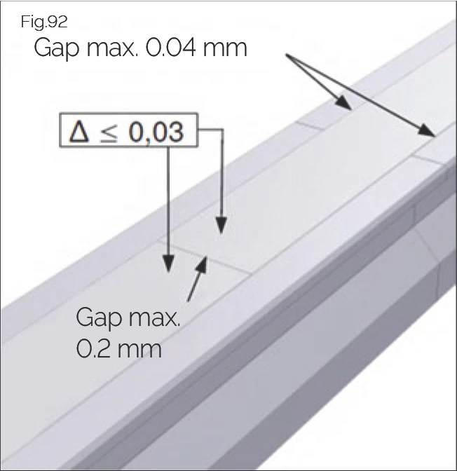
- Install all further strips so that they are seamless at each joint (gap size < 0.2 mm).
Alignment
Cover strips and guide rails are not the same length in the case of multi-part guide rails. Always install strip and guide rail joints offset by approx. 70 mm.
Completing installation of one-part and multi-part strips
- Check that the strips have been positioned correctly and consistently and are flush with the guide rail/s:
- The cover strip has a slight upward curvature, with its edges touching the guide rail surface.
- The permissible gap size between guide rail and cover strip is 0.04 mm.
- Strip height including curvature is max. 0.6 mm.
- Height difference between cover strips at butt joints is max. 0.03 mm.
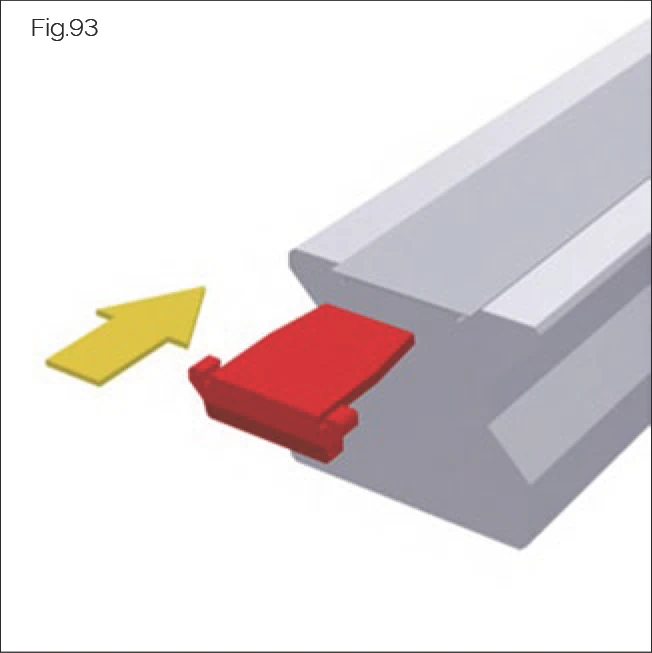
- Slide end pieces into the gap between cover strip and guide rail groove at each end of the guide rail until they stop.
- Lightly moisten the full guideway surface with the MONORAIL guideway lubricant.
NOTE: In the case of cover strips with a length < 600 mm, secure the strip ends with a steel bracket instead of the end pieces (see next section "Steel securing bands").
Steel securing bands
In cases of increased mechanical stress, e.g. in an open swarf area, the strip ends can be secured with a steel bracket in place of the red plastic end pieces. In this case, the protruding strip ends must be severed straight and burr-free and a threaded fixing hole introduced into the frontal end of the guide rail. Retrofitting of steel securing bands is only recommended if the guide rails have been inductively hardened. For dimensions of the securing bands and the threaded fixing hole, see "Appendix".
Steel securing bands are not part of the standard cover strip delivery package and must be ordered separately.
Disassembly
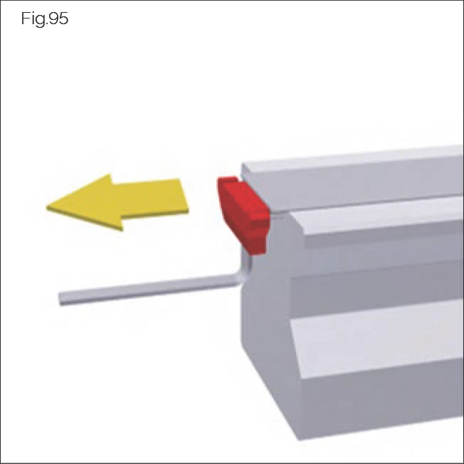
- Removing the end pieces:
- Hook an Allen wrench into the underside of the end piece.
- Pull the end piece out of the groove, pulling parallel to the guide rail.
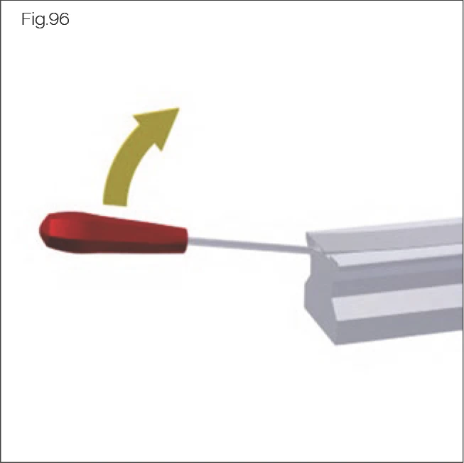
- Use a screwdriver to lift the cover strip a few millimetres out of the groove at one end of the guide rail.
- Take hold of the strip end by hand and lift it.
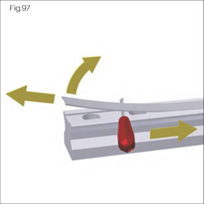
- Insert the screwdriver laterally between the guide rail and the cover strip.
- Slide the screwdriver along the length of the guide rail, lifting the cover strip. Take care not to bend or twist the strip. Do not allow the cover strip or guide rail to become scratched.
→ The cover strip is freed from the groove.
- Uninstall the cover strip from the full length of the guide rail.
- Check the cover strip for damage:
- Straighten cover strips that are slightly bent.
- Replace cover strips that are strongly bent, twisted, scratched, or otherwise damaged.
- Always replace end pieces. End pieces can become damaged during disassembly or lose their retaining force.
7.3 Removing the Protective Installation Film for Additional Wipers (Optional)
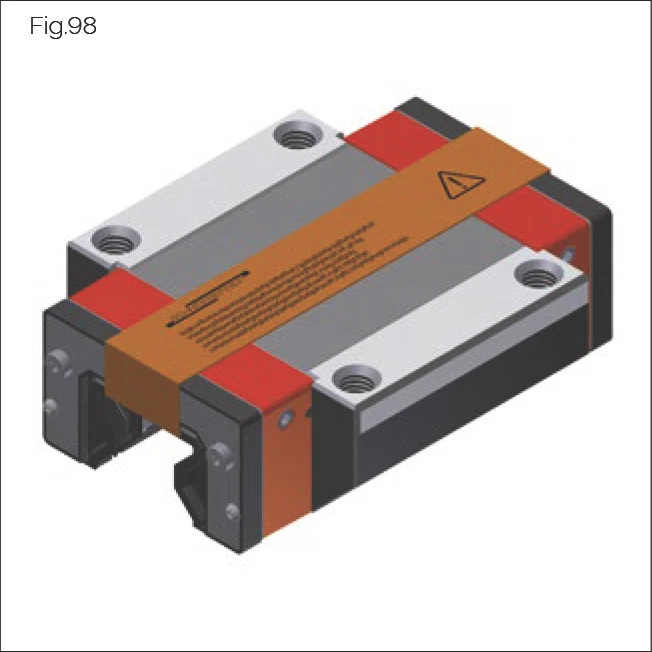
Fig.98
Carriages with ZBV/ZCV additional wipers are delivered with an installation protection film if the rails are screw-fastened from above and the fixing holes covered with plugs. The installation protection film protects the sealing lips during installation and should only be removed once the guide rail fixing holes have been sealed.
ATTENTION!
Risk of material damage posed by sliding carriages over the edges of open guide rail fixing holes!
Additional wipers can become damaged.
- Only remove protective installation film once fixing holes have been sealed.
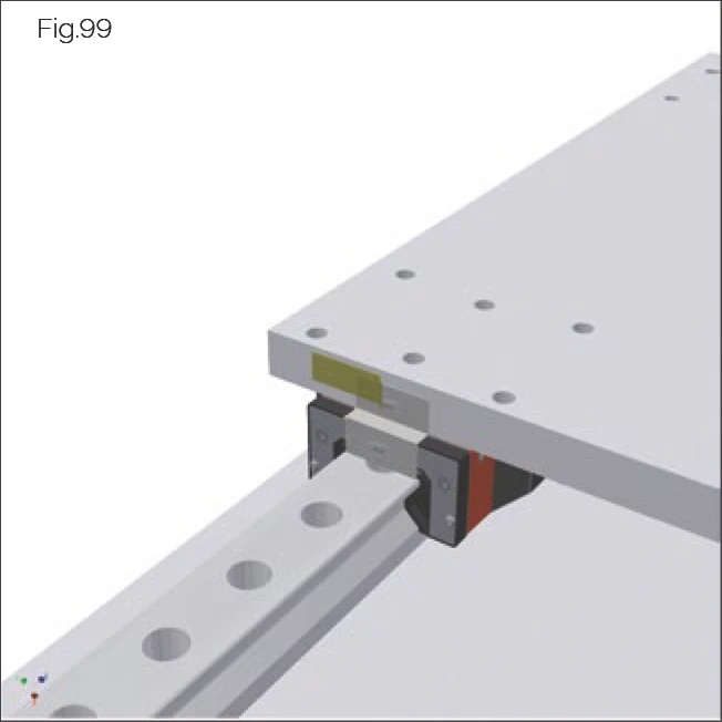
Fig.99
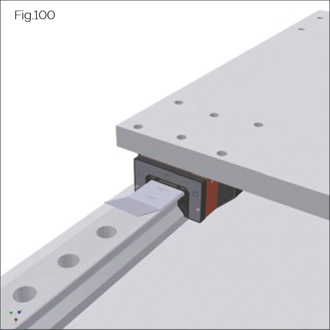
Fig.100
Pull the protective installation film away from the carriage in the direction of the guideway.
7.4 Lubrication
Lubrication Connections
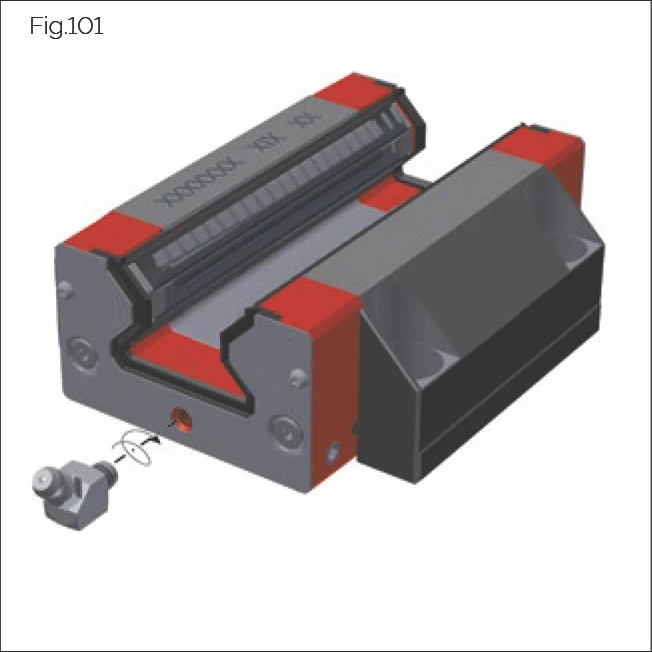
Fig.101
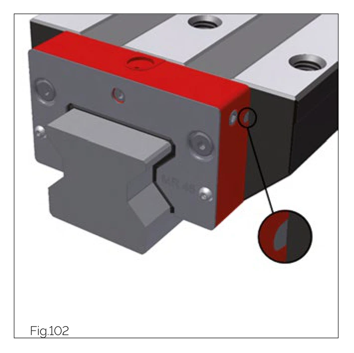
Fig.102
General
- Lube connections are plastic threads. Exercise caution when inserting lube connection pieces.
- Maximum tightening torque = 0.5 Nm.
- Recommended screw-in depth into front plate = 4 mm.
- Lube connection pieces with conical thread: max. screw-in depth accords with thread length.
Lubricant Distribution
Carriages are available with standard lubricant distribution and with separated lubricant distribution.
In the case of standard lubricant distribution, all four running surfaces are supplied with a single lube connection. The lubricant is distributed to all tracks in the front plate and redirection units.
In the case of separated lubricant distribution, two lube connections supply the right and left tracks separately.
MONORAIL MR includes a pin indicator which indicates whether a front plate is built for standard or separated lubricant distribution:
- Black pin - standard lubricant distribution.
- Grey pin - separated lubricant distribution.
In order to convert MONORAIL MR carriages from standard to separated lubricant distribution, the front plate must be fully replaced.
Installing the Lube Connection Pieces
- Ensure that the lube connection in the front plate is open.
- Screw the lube connection pieces into the carriages.
- When lubricating from above, place the sealing ring included into the depression in the front plate and if necessary strengthen its grip by applying some lubricating oil.
- If a centralised lubricating system is available, connect the carriage to the centralised lubricating system.
Initial Lubrication (Carried Out by Customer)
The initial lubrication supplies the rolling elements with lubricant. It also provides the wipers of the carriage with protection and a corrosion protection. A thin film of lubricant on the guide rails reduces lubricant consumption at the start of operation, as any surface roughness on the guide rail will be pre-filled with lubricant.
For lubricant quantities, see "Amount of lubricants" on page 77.
Apply the initial lubrication to the carriages in accordance with the following procedure:
- Lightly moisten the guide rails with the guideway lubricant.
- Slide the carriages more than three times their length several times.
- Insert the required quantity of lubricant into the carriages.
SPL Lubrication Plate
ATTENTION!
Risk of material damage posed by improper handling of contact elements!
The oil-delivering contact elements are slightly pre-stressed and can be destroyed by improper handling.
- Carefully slide the lubrication plate over the end of the guideway.
- Only install lubrication plates when the carriage is on the guideway.
General
- Lubrication plates are delivered ready for installation, i.e. filled with oil.
- When using lubrication plates on the carriages, carry out an additional filling with grease. For recommended lubricant quantities, see "Amount of lubricants" on page 51.
- Only use lubrication plates in pairs.
- Do not use lubrication plates if the guideways are in direct contact with coolant.
- Use covers to protect guideways from dirt, swarf, and coolants, using additional wipers if necessary.
- Apply regular lubricating strokes over the full travelling distance of the axis.
- Include the lubrication plates in the machine maintenance plan:
- Check the wipers regularly for wear.
- Check the oil film on the guide rail track.
- Carry out lubricating strokes.
- Refill the SPL.
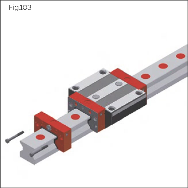
Fig.103
Installation
- Loosen and remove the upper screws on the standard front plate (In the case of MONORAIL MR the lower screws remain screwed into the carriage, whereas in the case of MONORAIL BM the front plate must be held).
- In the event that the central lube hole in the front plate is closed with a plastic protective plug, remove this and replace it with a set screw.
- Carefully slide the lubrication plate over the guide rail end to the carriage.
- Secure the lubrication plate using the long screws included in the SPL delivery.
Replacement
- Loosen and remove the screws from the lubrication plate. In case of BM, take care to hold the front plate in place as rolling elements may otherwise be lost.
- Remove the lubrication plate from the guideway end.
- Carefully slide the new lubrication plate over the guideway end to the carriage.
- Fasten the new lubrication plate.
Installing ZCV/ZBV Additional Wipers or ASM/ABM Metal Wipers
- Remove the screw plug from the front central lube hole. For installation of the additional wiper, see "ZCV/ZBV additional wipers" on page 66. For installation of the metal wiper, see "Replacing ASM/ABM metal wipers" on page 67.
- Install the additional wiper and/or metal wiper onto the lubrication plate using the screws included.
- Re-seal the front central lube hole with the removed screw plug or using a lube nipple.
Refilling
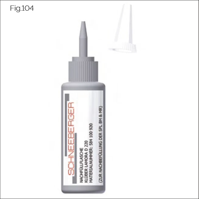
Fig.104
The lubrication plate can be refilled via the front, middle, or lateral lube holes (size MR 25 only from the front). For ordering information and dimensions, see the Technical data section of the MONORAIL catalogue. To do this, remove the applicable screw plug using an Allen wrench and replace it with a lube nipple. A conical lube nipple is available for order as an accessory.
Refilling is carried out for example using an oil press via a conical or flush type lube nipple screwed into one of the prepared lube holes in the front, the middle, or laterally. A special oil bottle offered by SCHNEEBERGER as an accessory can also be used. Refilling is carried out in this case directly into the SPL lube hole, eliminating the need for a lube nipple.
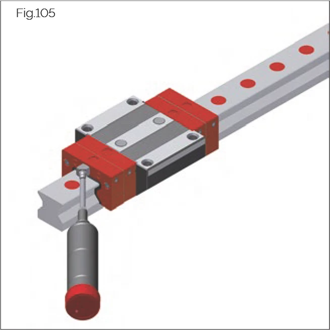
Fig.105
Lubrication plates are refilled using the oil quantities in the table (see "Amount of lubricants" on page 77) in approximately 4 to 5 stages, depending on the size and condition of the lube connection used.
In order to achieve optimal refilling results, it is recommended that both lateral lube connections are used.
An interval of approx. 5 minutes should be left between each individual filling stage.
Oil release should be checked at the felt contact points with the guideway.
The filling quantity generally depends on the drainage rate of the lubrication plates.
Refilling SPL-MR
See "Lubricating volumes for SPL refilling" on page 78.
Refilling SPL-BM
See "Lubricating volumes for SPL refilling" on page 78.
The lubrication plates should be refilled in accordance with the applicable operating conditions. As a guideline, the following refilling intervals can be assumed:
- BM 15 - BM/MR 35: 2,500 km
- MR/BM 45 - MR 65: 5,000 km
An accurate determination of the intervals can only be achieved under actual operating conditions. More frequent refilling will be required under unfavourable conditions, or in an unfavourable climate or working environment. Irrespective of the distance travelled, refilling is necessary after a maximum of 12 months operation.
7.5 Laying the Electronics Housing and Cables
Electronics Housing
The sensor unit of the measuring system (excluding AMSA 3L) has a separate electronics housing. The electronics housing is mounted near the read head at the machine slide and has an LED display on its front for indicating various operating states.
The electronics housing should be installed in accordance with the following points:
- Fit the electronics housing so that the front of the housing and the diagnostic LED (in the case of AMSD 3B/4B, AMSABS 3B) are easily accessible for servicing.
- Do not lay cables from and to the housing under tension.
- Do not fall below the minimum bending radii (see "Cable bending radii" on page 78).
Cables
Shielded cables are used as KAO extension and connecting cables between the measuring system and controller.
When laying cables for the measuring system, the following points must be observed:
NOTE: Do not lay cables next to interference sources, e.g. magnetic fields from voltage supplies, mains electricity lines, motors, valves, relays and their feeds.
- For cable conduits, ensure that the dimensions of the mounting base comply with the catalogue or connector diameter.
- Ensure an adequate distance from cables carrying interference sources: 0.1 m.
- Employ a grounded separation screen if metal cable ducts are used.
- Ensure a minimum distance of 0.2 m from storage chokes in switched mode power supplies.
- Separate hydraulic hoses and electrical cables.
- Lay the read head cable (4) as statically as possible, e.g. not in a cable carrier (6).
- Use an extension cable (5) as a cable carrier (6).
- Do not use sharp-edged ducts.
- Lay cables without any tensile load.
- Do not fall below the minimum bending radii (see "Cable bending radii" on page 78).
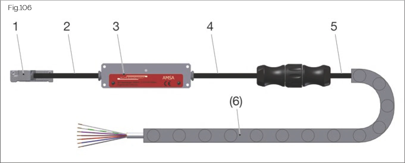
Fig.106
The cable carrier (6) is not included in the scope of delivery.
Connecting the Measuring System and Suitable Extension Cable Length
MONORAIL AMS is connected directly to the drive controller of the axis. Extension cables with a length of up to 50 m can be used depending on the model of sensor unit and controller used.
7.6 Installing a FBM/FBB Bellows - Optional
Bellows are mainly used as an additional form of protection for carriages against dust and splashes of water.
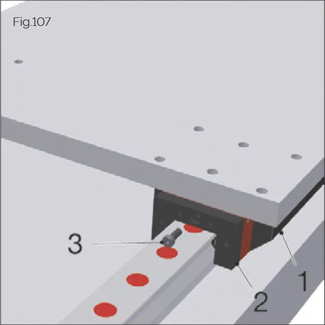
Fig.107
- Prior to installing the bellows, ensure that guide rail fixing holes are sealed with plugs and the cover strip.
- Slide the machine slide into approximately the centre of the stroke.
- Insert the adapter plate (2) in front of the first carriage (1). Ensure that the countersink into the fixing hole is on the side facing away from the carriage.
- Secure the adapter plate to the middle lube connection thread of the front plate using the central screw (3) (max. tightening torque 0.5 Nm).
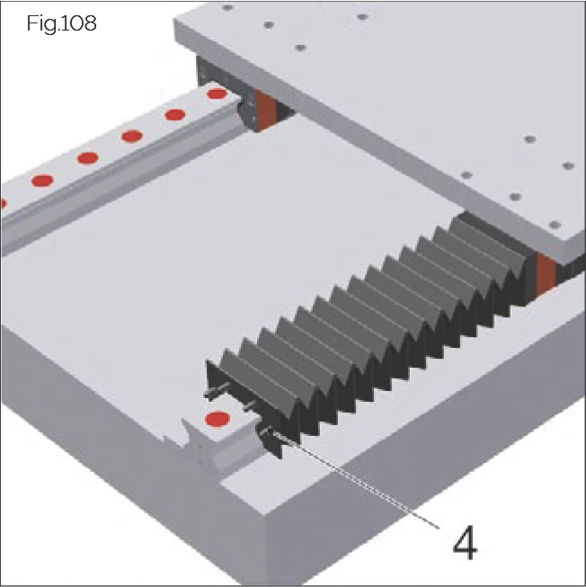
Fig.108
- Mount the pre-assembled bellows (with supporting frame and rivets) onto the guideway.
- Snap the rivets (4,7) at the end of the bellows into the corresponding holes in the adapter plate.
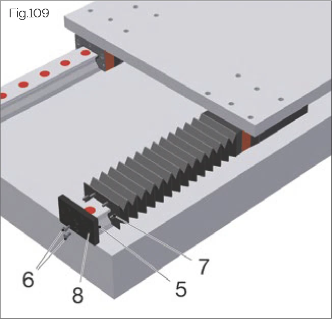
Fig.109
- Insert the end plate (5) at the end of the guideway. Ensure that the side with the countersink into the fixing holes is on the side facing away from the carriage.
- Secure the end plate using the screws included (6).
- Snap the rivets (4,7) at the end of the bellows into the corresponding holes (8) in the adapter plate.
- Check that the bellows slide well on the guideway and that the folds are not too strongly compressed or stretched in the slide end positions.
7.7 Checking the Results of the Installation
Following installation, check that the guideway and accessories have been installed are functioning correctly:
Push Force
Move the machine slide by hand over the full stroke, ensuring that push force remains constant and that the movement is jerk-free.
Lubrication
Ensure that the lubricant lines are properly connected and vented, and that the carriages are sufficiently supplied with lubricant.
In order to test lubricant circulation, activate the lubricant supply whilst simultaneously moving the carriage on the guideway. A thin film of lubricant will appear on the guideway.
Ensure that no lubricant is leaking from the lubricant lines, the lube connection parts, or from between the front plate and carriage body.
Cover Strip and Plugs
NOTE: Burrs and protruding parts of sealing elements can damage the wiper lips of the carriages during operation.
Ensure that cover strips and plugs are positioned consistently and flush with the guideway.
- Cover strips must lie cleanly and without gaps on the guide rail surfaces and must not be bent. The ends must be secured with a bracket or end pieces.
- Plugs must be fitted flush and parallel with the guide rail surface; they must not protrude or sit too deeply. Ensure in the case of plastic and brass plugs that all residual swarf or burrs have been removed.
Front Plates and Additional Wipers
Check that carriage front plates and accessory parts as well as additional wipers are positioned and functioning correctly.
Check that lubricant applied to the guide rails has been wiped off cleanly. Ensure that lubricant on guide rail surfaces that has been passed over does not form any streaks.
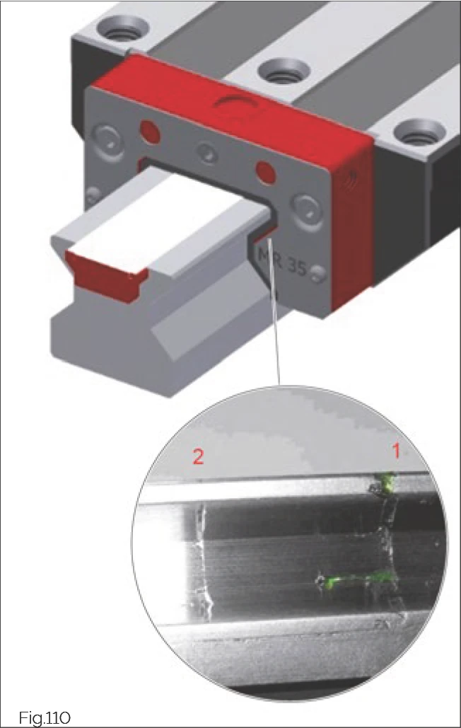
Fig.110
Checking Wipers
- Clean lubricant and dirt particles from guide rails and wiper sealing lips.
- Apply (ideally coloured) lubricating grease or oil to the tracks of the guideway and distribute evenly with a cloth.
- Move the carriage with wipers a few centimetres over the moistened guideway.
→ Effect of wipers is clearly recognisable (1), excess lubricant is wiped ahead.
- Move the carriage back to its starting position.
→ The lubricant on the sealing lip is drawn backwards.
- Move the carriage forward again (not as far as moved in the first stroke).
→ A thin, continuous line of lubricant is visible on the guideway track (2).
NOTE: An absent or interrupted line of lubricant is indicative of an improperly-fitting wiper.
The wiper must be exchanged if this is the case.
Metal Wipers
The wipers must form an even gap around the guide rail profile and should not make contact with the guide rail at any point. Use special metal wipers for AMS systems.
Check that the wipers are correctly positioned using a feeler gauge and by moving the machine slide.
Bellows
Check that the bellows are correctly fitted to the adapter plate and end plate.
Ensure that the bellows are able to move freely.
Traverse the machine axis, checking that the bellows slide well along the guideway.
Check that the folds are not too strongly compressed or stretched in the slide end positions.