Chapter 6 Installation
Installation
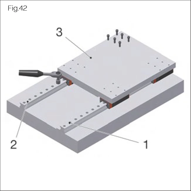
6.1 MWM Installation Carriage
The installation carriage can be used to perform the following installation work:
- Position the carriage above a joint so that one of the two outer fixing holes of the guide rail is visible.
- Position the carriage above the fixing hole of the other guide rail, insert and tighten the screw.
- Move the installation carriage gradually through the guide rail.
- Measure the lateral position using a laser or dial indicator.
- Position the carriage above the central guide rail fixing hole.
- Press the guide rail into the required position.
- Insert and tighten the guide rail fastening screw through the central fixing hole from above.
The installation carriage is available as a SCHNEEBERGER accessory.
Aligning Butt Joints of Multi-Part Guide Rails
In the case of multi-part guide rails, the butt joints must be correctly aligned to ensure smooth carriage movement.
Adjusting Guide Rails Without Lateral Reference
When there is no lateral reference, use the installation carriage and measuring instruments to adjust the lateral position of the guide rail.
6.2 Handling Carriages
Danger!
Risk to life posed by falling machine elements!
Possible consequences include death and serious injury.
- Ensure that additional fall protection is provided.
- Never remove the front plate from MONORAIL BM.
- Rolling elements must under no circumstances be allowed to fall out of the carriage.
- In order to prevent rolling element loss, always store and transport carriages on transport/assembly rails.
- Always keep carriages on the guide rail. Mount carriages onto and dismount them from the transport rail using an assembly rail.
- If optionally implementing paired systems, ensure that the carriages of different guide rails are not interchanged.
- In the case of carriages with a read head, always remove the read head before mounting the carriage onto an assembly rail.
- Protect individual carriages from dirt and the loss of rolling elements.
- Always brace the locating surfaces of the carriage against the locating surfaces of the mounting plate. The locating surface of the carriage is the side that has been ground.
- Arrange for reworking of front plates to alter the lube connection to be carried out through SCHNEEBERGER.
- Before mounting carriages onto the guide rail, remove the factory-applied protective coating. In the case of repeated movement of the carriages back and forth on the guide rail, protect wipers from damage caused by sharp-edged rail fixing holes.
- Always tighten fastening screws using a torque wrench (for tightening torques, see "Screw tightening torques" on page 75).
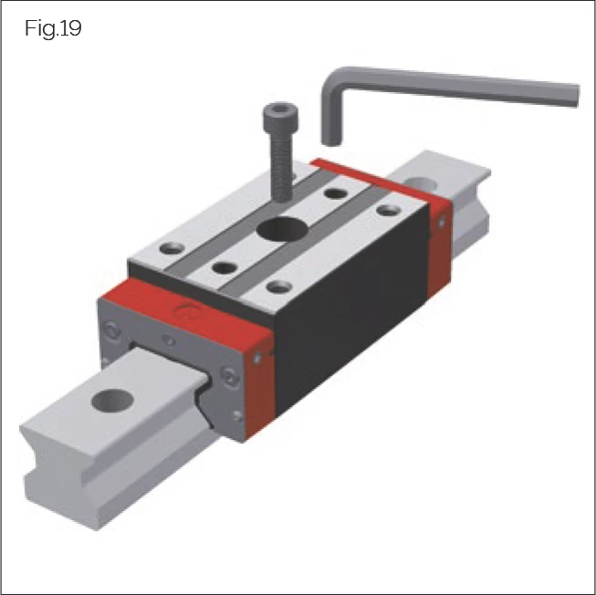
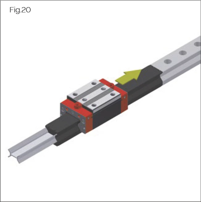
In the case of Monorail MR 100, a metal transport rail is used. This must be replaced prior to installation using an assembly rail, in accordance with the following procedure:
- The transport rail must be pushed out of the carriage using the assembly rail.
- Removal of the transport rail without replacement with an assembly rail may result in the loss of rolling elements.
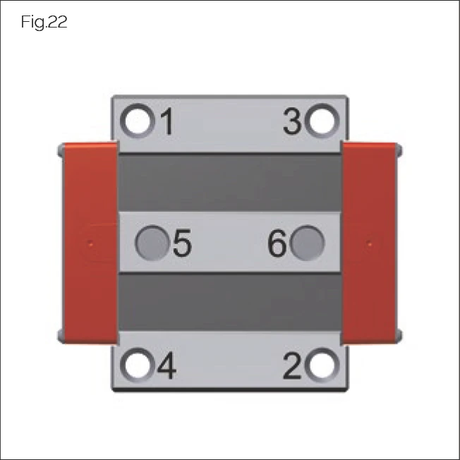
When fastening a connecting structure to a carriage, tighten the screws in accordance with the following steps:
- Tighten the screws with 50% of the nominal torque. See numbering for sequence.
- Tighten the screws with 100% of the nominal torque. See numbering for sequence.
Carriage Installation Video Tutorial
MONORAIL Carriage Installation
Demonstrates how to properly install the carriage onto the rail, including alignment tips and precautions. For MR, BM series carriages. | Duration: ~1 min
6.3 Handling Guide Rails
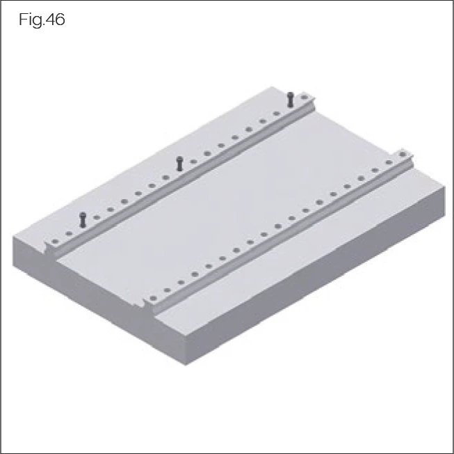
Ensure prior to installation that the guide rails, machine bed, mounting plate, and fastening screws are all at the same temperature.
Always brace the locating surface of the guide rails against the locating surface of the machine bed. The locating surface of the guide rails is the surface on the opposite side of the SCHNEEBERGER logo and part numbering.
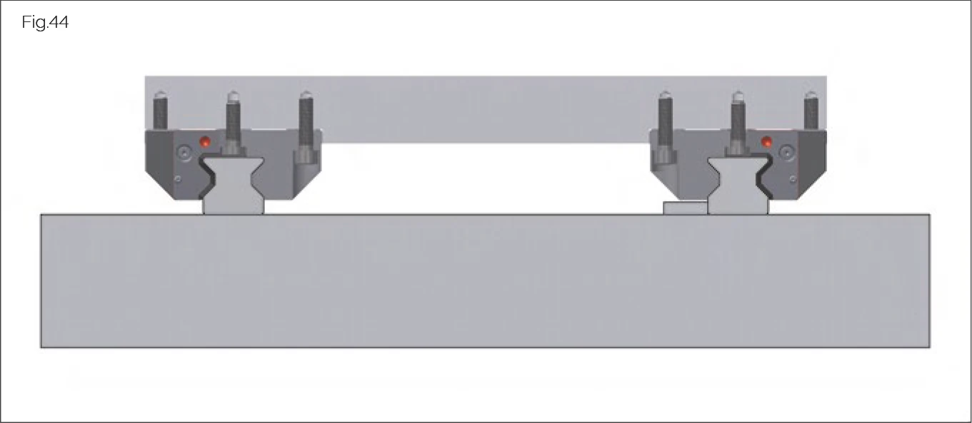
For optimal screwing force, proceed as follows:
- Lubricate the screw head rests and threads of the fastening screws with grease containing MoS2.
- Tighten the fastening screws in accordance with the figure on the left.
- Always tighten fastening screws using a torque wrench (for tightening torques, see "Screw tightening torques" on page 75).
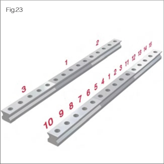
6.4 Handling Multi-Part Guide Rails
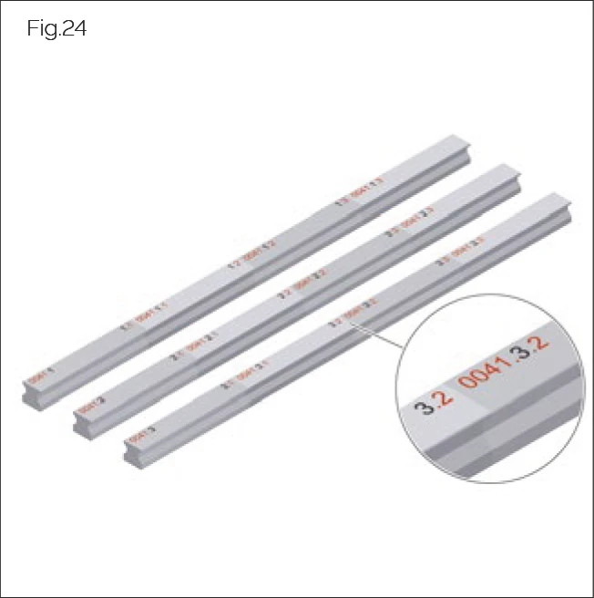
Multi-part guide rails are marked with a number at their joints. In the case of a matched design, the guide rails are also marked with a set number at the start of the rail. The guide rail with the set number index 1, or with the butt joint number 1 is designated as the reference rail.
Installation procedure:
- Install individual rail segments alternately or consecutively from the line centre outwards.
- Install the guide rails so that the butt joint numbers match.
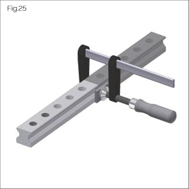
Proceed as follows according to the rail system:
- In the case of multi-part rails without a locating surface in the machine bed, align the butt joints using a fixing bridge or MWM installation carriage.
- In the case of guide rails with locating surfaces on the machine side, lay the guide rails with their locating side against the locating surface.
- In the case of MONORAIL AMS, install the guide rail with the magnetic measuring scale as the reference rail. MONORAIL AMS guideways have a designation on the guide rail and a carriage with a read head.
ATTENTION!
Risk of material damage posed by sharp edges!
Carriage cross wipers can be damaged during operation by sharp-edged rail fixing holes.
- Ensure that rail fixing holes are covered.
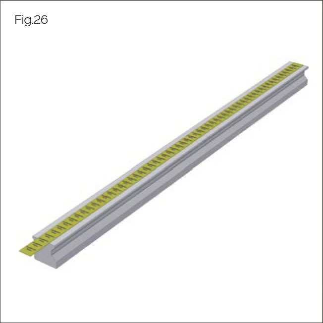
Prior to carriage installation, cover the mounting holes on the upper surface of the guide rail with a suitable adhesive tape. The adhesive tape protects the cross wiper of the carriage from damage by sharp-edged fixing holes.
6.5 Handling Measuring Systems
6.5.1 Handling Magnetic Fields
Failure to observe the points specified in this section may result in material damage.
ATTENTION!
Risk of material damage posed by magnetic fields!
Incorrect handling of AMS rails in relation to magnetic fields may result in material damage.
- Observe the points in the following section.
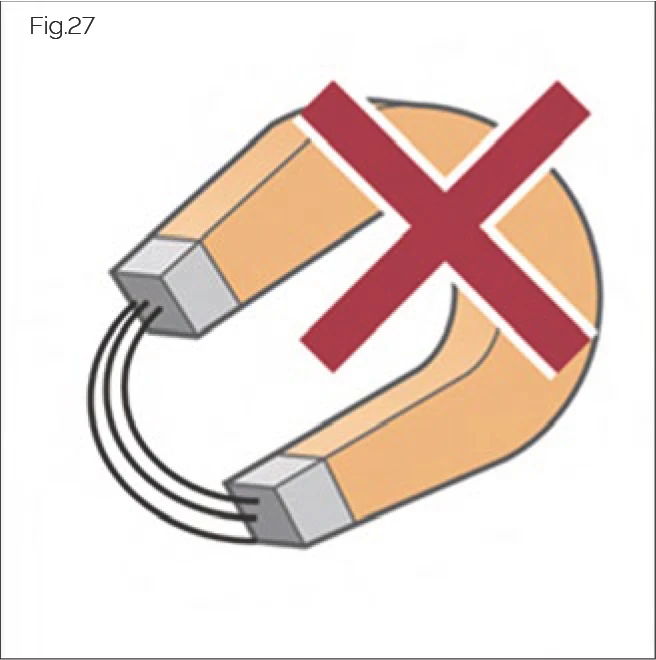
Only non-magnetic materials should be used in the direct vicinity of the measuring scale and the read head.
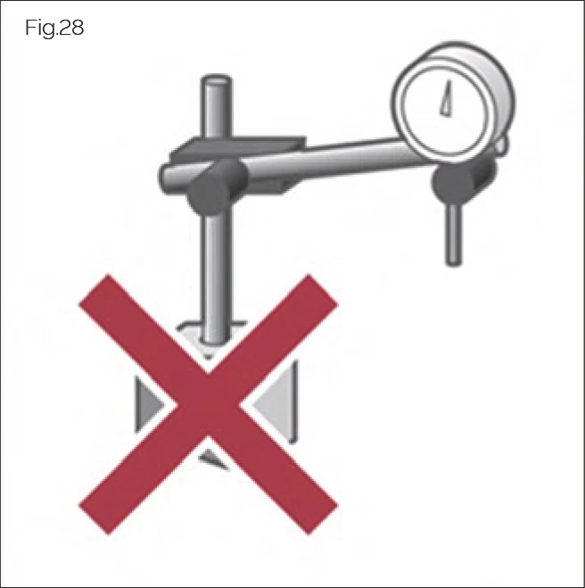
Only use non-magnetic aids to transport and align AMS guideways.
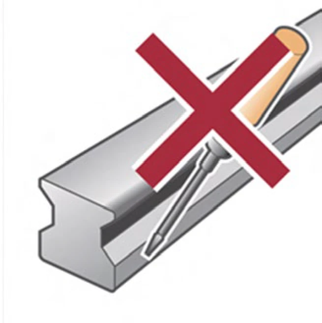
Avoid direct contact between tools and the magnetic measuring scale.
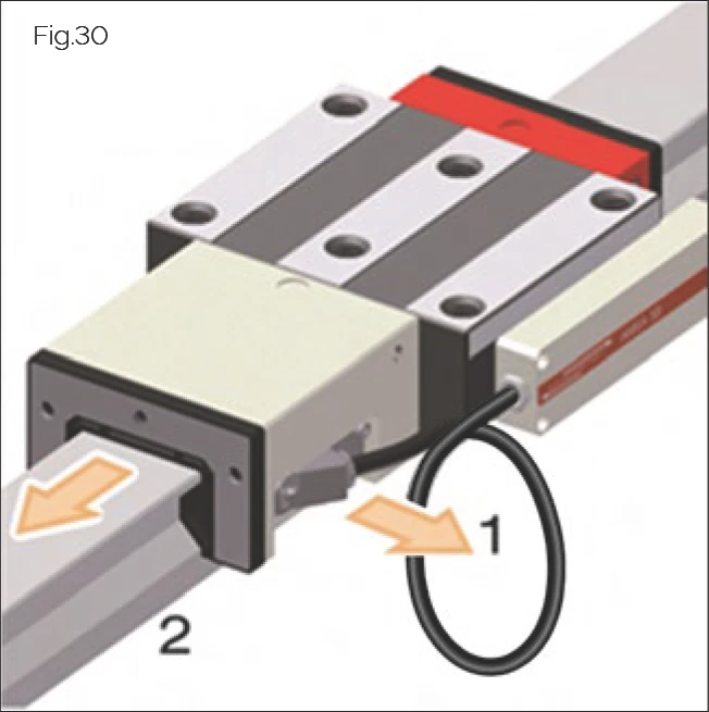
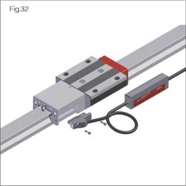
Disassemble the AMS read head (1) before mounting or dismounting the MONORAIL carriage onto or from the guideway (2).
- Read head
- Guideway
6.5.2 Installing and Connecting the Read Head
ATTENTION!
Risk of material damage posed by incorrect insertion of read head!
May result in damage to sliding parts.
- Do not allow any particulates to become caught between the sensor slider and the scale.
- Do not allow sliding parts to come into contact with the read head.
- Do not damage the sliding parts.
Installing the Read Head
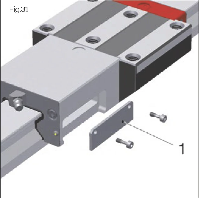
In the case of MONORAIL AMS systems delivered without a read head, the housing is sealed with a cover plate (1). This must be removed prior to read head installation.
| Type | AMS 3B | AMS 4B | AMSA 3L | AMSABS 3B/4B | AMSABS 3L |
|---|---|---|---|---|---|
| Screws | 2x ISO 4762 M3x10 - A2 (self-locking) | 2x ISO 4762 M2.5x10 - A2 (self-locking) | 2x ISO 4762 M4x20-A2 | 2x ISO 4762 M3x10 - A2 (self-locking) 1x ISO 4762 M3x4 - A2 (self-locking) | 2x ISO 4762 M3 x 10 - A2 (captive) |
| Tightening torques | 1.1 Nm | 1.1 Nm | 1.1 Nm | 1.1 Nm | 1.1 Nm |
Read Head Installation Video Tutorial
AMS Reading Head Installation
Shows the installation procedure for AMS integrated measuring system reading heads, ensuring stable signal and precise positioning. For all AMS series. | Duration: ~2 min
Connecting the Read Head
ATTENTION!
Risk of material damage posed by short-circuit currents!
The electronics in the read head are vulnerable to destruction by short-circuit currents.
- Before connecting the cable, disconnect the power supply and ensure that it cannot be restored without authorisation.
Connecting directly to the drive controller:
Connect the read head plug to the drive controller and tighten the swivel nut by hand.
6.5.3 Installing AMS 3B, AMS 4B and AMSA 3L Product Versions
- Where necessary, remove the cover plate from the housing.
- Carefully insert the read head into the lateral recess of the housing.
- Insert and tighten the fastening screws. No additional adjustment is necessary. The tightening sequence is irrelevant in this case.
6.5.4 Installing AMSABS 3B, AMSABS 4B Product Versions
- Where necessary, remove the cover plate from the housing.
- Activate the battery, see 5.7 Preparing the measuring system for installation on page 17.
- Carefully insert the read head into the recess in the housing using a rotating motion.
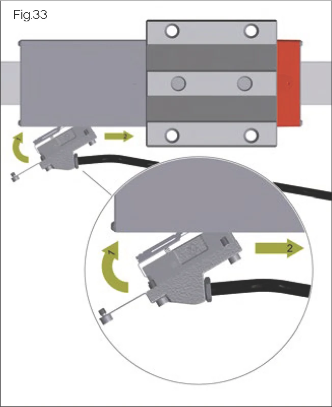
- Swivel the distance reference cover plate (1) for mounting.
- Slide the read head (2) towards the carriage until it stops and hold it down (see Figure). This ensures that the measuring system automatically recognises its absolute position during installation and is ready to use immediately afterwards. Once the controller is switched on, the LED will light up green.
- Swing the distance reference cover plate (1) to the designated position and hold it down.
- The sensor unit is delivered with self-locking screws. Tighten these in accordance with the torque values (see "Installing and connecting the read head" on page 25). Tighten the screws in the following order: A, B, C (Fig. 33).
6.5.5 Installing AMSABS 3L Product Version
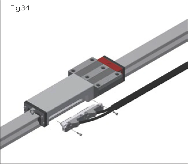
- Remove the cover plate on the add-on housing, if necessary.
- Activate the battery (see "5.7 Preparation for mounting the measuring system" on page 17).
- Carefully insert the read head into the recess on the side of the add-on housing.
- Insert and tighten the fastening screws. Additional adjustment work are not necessary. The order in which the screws are tightened is irrelevant.
6.6 Installation Options
6.6.1 Installation Option 1
Installation option 1 is applicable in cases in which locating surfaces are present for one guide rail and for one carriage.
- Brace the reference rail (1) against the locating surface of the machine bed and fasten with screws (see "Handling guide rails" on page 21).
- Adjust the opposite guide rail (2) so that it is parallel and pre-fasten it by lightly tightening its screws.
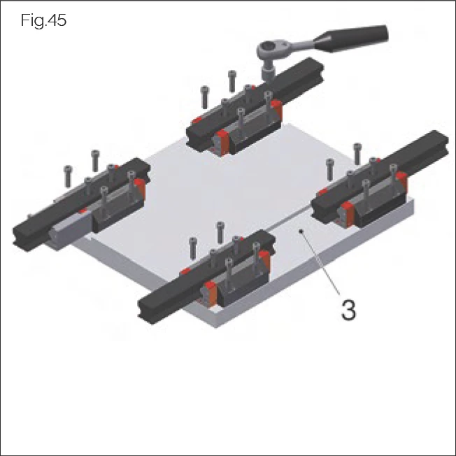
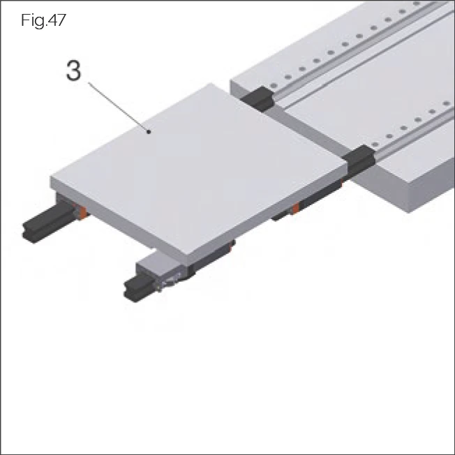
- Place the mounting plate (3) on the carriage and lightly tighten its fastening screws.
- Brace the mounting plate (3) against the locating surfaces on the carriages on the secured reference rail and fasten its screws.
- Brace the opposite guide rail (2) against the locating surface of the mounting plate and tighten with specified torque.
6.6.2 Installation Option 2
Installation option 2 is applicable in cases in which locating surfaces are present for both guide rails and for one carriage.
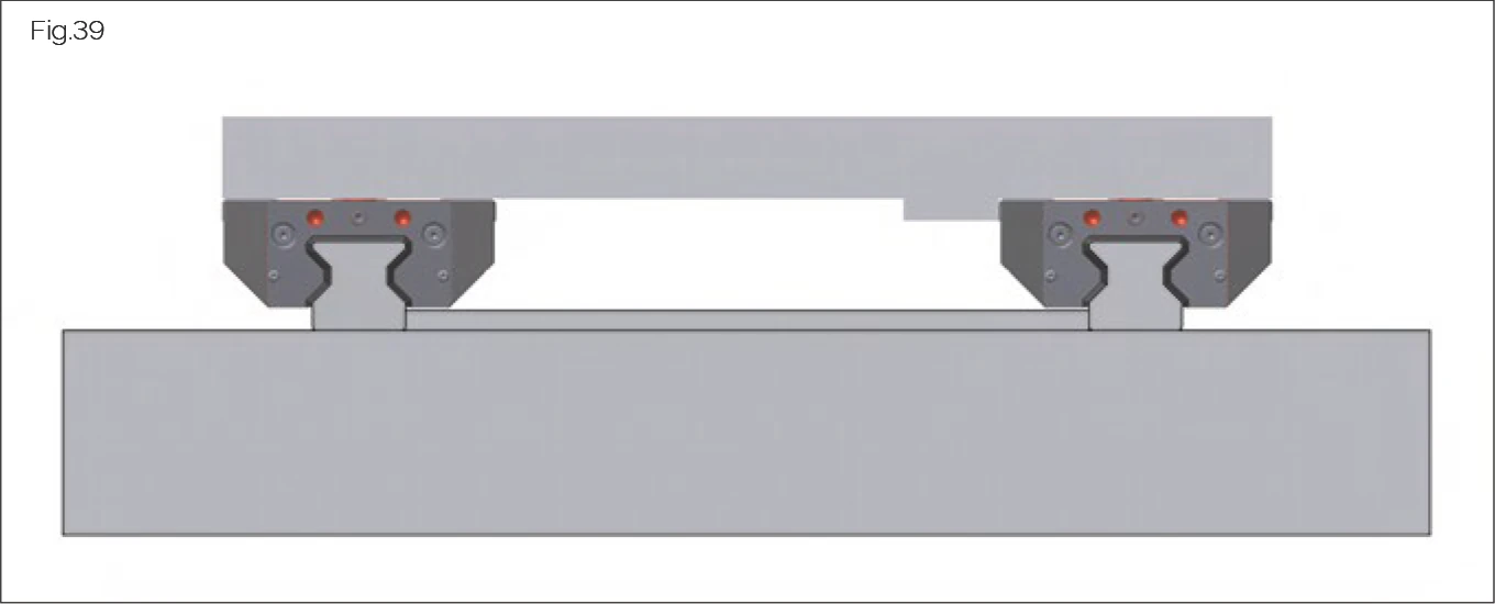
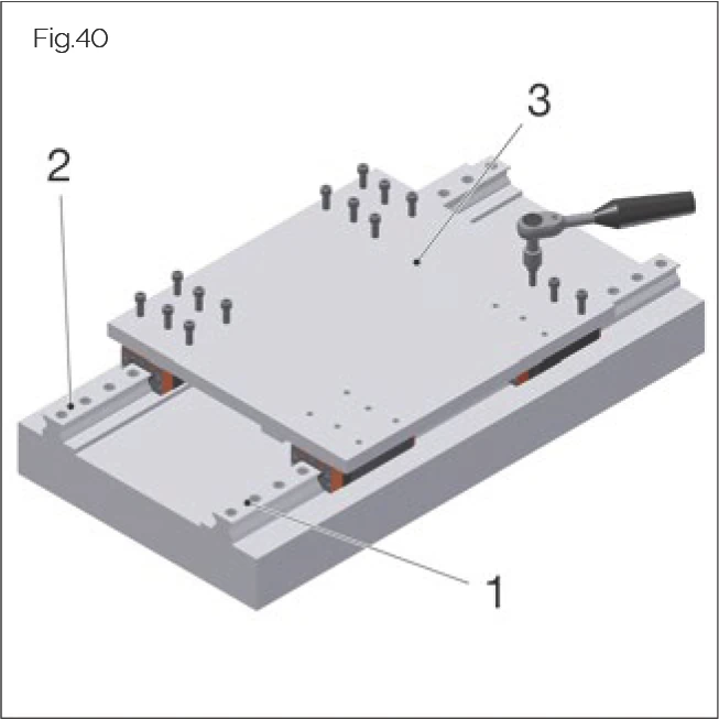
- Brace both guide rails (1), (2) against the locating surfaces and fasten with screws (see "Handling guide rails" on page 21).
- Install clamping screws or clamping or wedge bars where required.
- Place the mounting plate (3) on the carriages and lightly tighten all fastening screws.
- Brace the mounting plate (3) against the locating surfaces of the carriages on the reference rail and fasten to both carriages.
- If carriages with additional wipers are protected by an installation protection film: prevent the protective film from slipping (see "Removing the protective installation film for additional wipers (optional)" on page 50).
- Slide the mounting plate (3) with carriages once over the full length of the guide rails.
- Fully fasten the mounting plate (3).
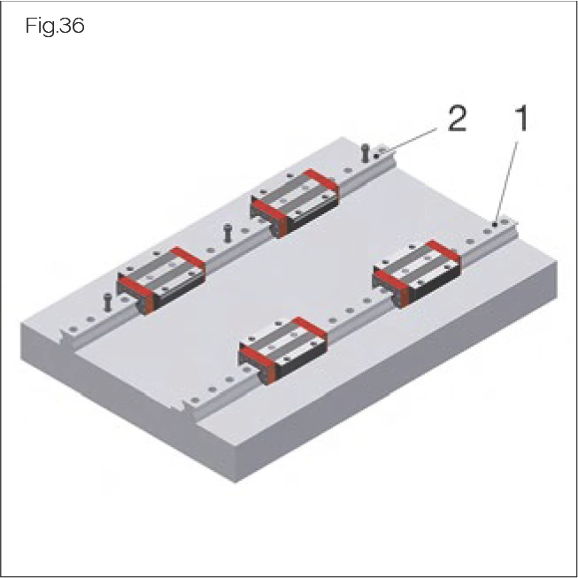
6.6.3 Installation Option 3
Installation option 3 is applicable in cases in which locating surfaces are present for one guide rail and for both carriages.
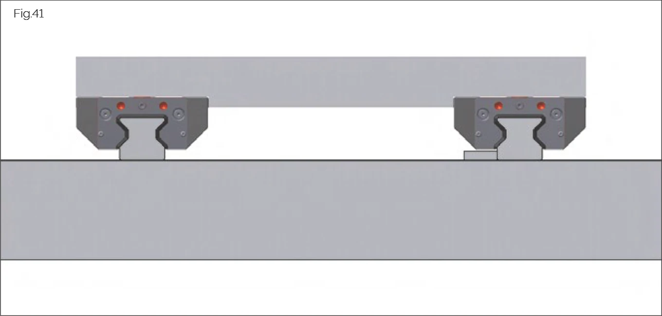
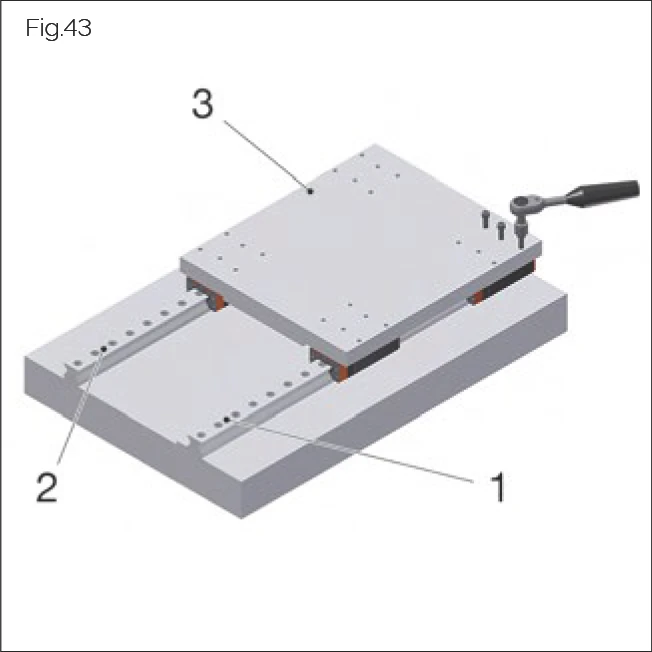
- Brace the reference rail (1) against the locating surface and fasten with screws (see "Handling guide rails" on page 21).
- Adjust the opposite guide rail (2) so that it is parallel and pre-fasten it.
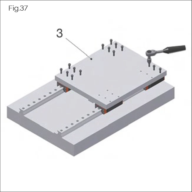
- Place the mounting plate (3) on the carriages and lightly tighten its fastening screws.
- Brace the mounting plate (3) against the locating surfaces of the carriages on the rails on each side and fasten with screws.
- If carriages with additional wipers are protected by an installation protection film: prevent the protective film from slipping (see "Removing the protective installation film for additional wipers (optional)" on page 50).
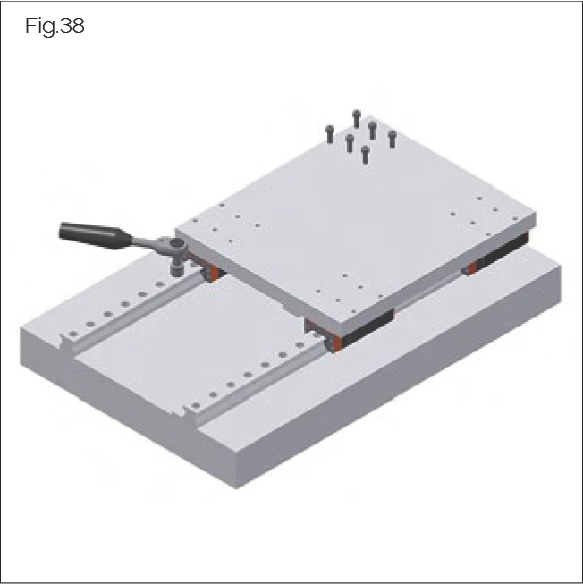
- Install clamping screws or clamping or wedge bars where required.
- Slide the mounting plate (3) with carriages back and forth and tighten fastening screws on the unsecured guide rail tightly against the carriage (see "Handling guide rails" on page 21).
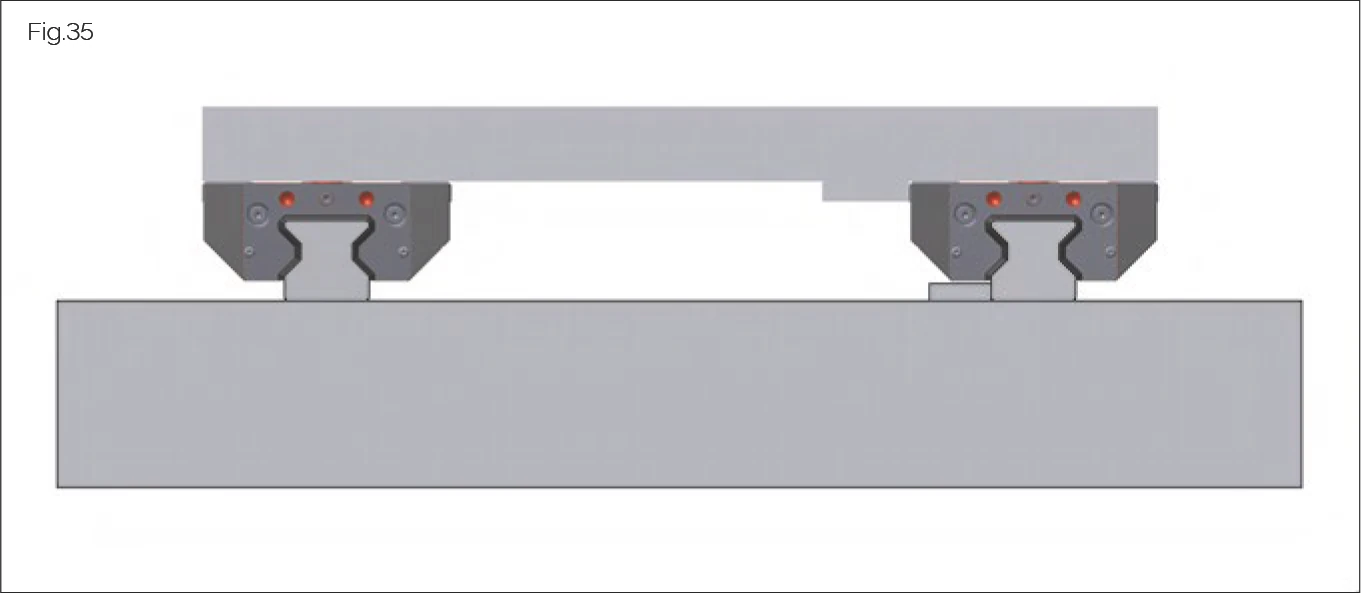
6.6.4 Installation Option 4
Installation option 4 is applicable in cases in which locating surfaces are present for one guide rail and for both carriages. In this option, the mounting plate is fastened with screws from underneath through the carriages.
- Remove the read head from the delivered system (see "Replacing the read head" on page 61).
- Dismount the carriages from their transport rails using an MRM / MBM assembly rail in each case. Take care that each carriage is identified with its corresponding guide rail.
- Brace the locating surfaces of the carriages (ground side) against the locating surface of the mounting plate (3) and fasten with screws.
- If carriages with ZCV/ZBV additional wipers are protected by an installation protection film: prevent the protective film from slipping (see "Removing the protective installation film for additional wipers (optional)" on page 49).
- Brace the reference rail (1) against the locating surfaces on the machine bed and fasten with screws (see "6.6.1 Installation option 1" on page 26).
- Install clamping screws or clamping or wedge bars where required.
- Adjust the opposite guide rail (2) so that it is parallel and fasten it by lightly tightening its screws.
- Mount the mounting plate with carriages onto the guide rails:
- Lay the assembly rails to the front ends of the system rails.
- Slide the carriages from the assembly rails onto the system rails.
- Slide the mounting plate with carriages back and forth and tighten the fastening screws of the unsecured guide rail tightly against the carriage (see "Handling guide rails" on page 21).
- Install the read head (see "Replacing the read head" on page 61).
6.7 Installing MONORAIL BZ
Install the system by following these steps:
- Remove loosely packaged parts and uninstalled cover strips from the transport crate.
- Lift the BZ out of the transport crate by hand or using suitable lifting equipment provided by the customer.
- Lift the BZ horizontally.
- Transport the BZ to the prepared installation location.
- Remove the protective film and clean the locating side and tooth tips.
- Lift the BZ to the installation position.
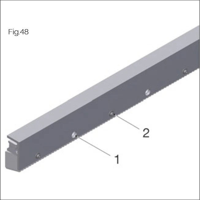
- Secure the BZ to the mounting points with screws:
- Pass the screws through the large holes in the profile (1).
- Lightly tighten the screws.
- Release the aluminum profile:
- Loosen the clamping elements (2) (do not unscrew the screws completely).
- Remove the profile with clamping elements.
- Lightly tighten the remaining screws to secure the BZ to the machine.
- Align the BZ.
- Tighten the screws using the specified torque (see page 75 "Screw tightening torques").
- Tighten the screws progressively from one side or from the center.
- If required, seal the screw countersinks with BRK plugs (see page 33 "MRK/BRK plastic plugs").