5 Commissioning
5.1 Signal Transmission
To increase noise immunity, we recommend using differential signals conforming to the RS-422 standard. Balanced signal transmission with opposing signal phases can virtually prevent interference. Virtually all modern drive controllers support this option.
Twisted pairs are used to transmit the signals (A+, B+, R+) and matching inverted signals (A-, B-, R-). At the receiver, the signal is generated by taking the difference between the two signal levels.
With single-ended signal transmission, the signal level changes relative to a reference potential. This type of signal transmission is more susceptible to interference. The signal amplitude in this case is half that of differentially transmitted signals.
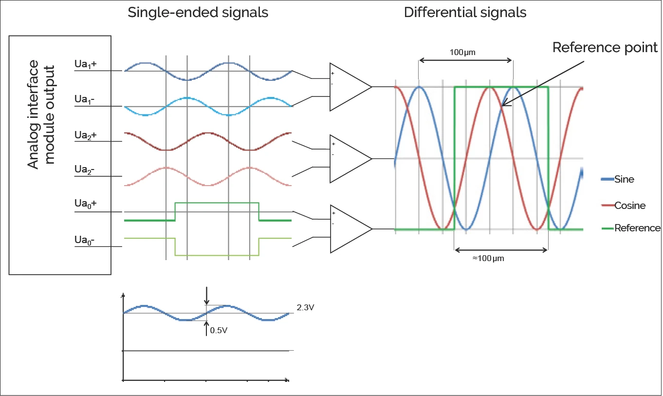
Analog output signals at the interface module. They can be used either single-ended (referenced to ground) or differentially.
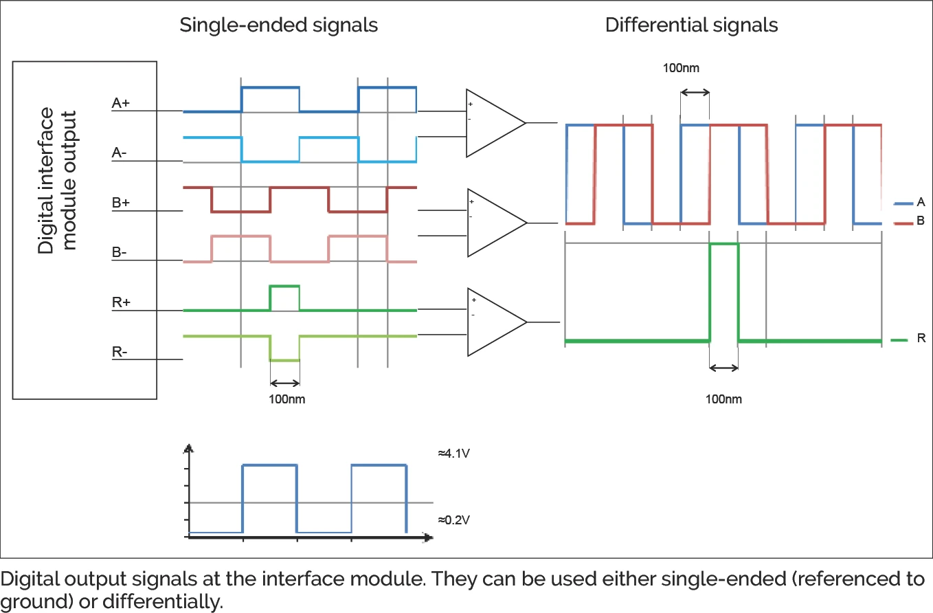
Digital output signals at the interface module. They can be used either single-ended (referenced to ground) or differentially.
The bus termination resistor for RS 422 should be 120 Ohms.
5.2 Pin Assignments
5.2.1 Analog and digital interface module
Male 9-pin D-Sub connector or solder terminals:
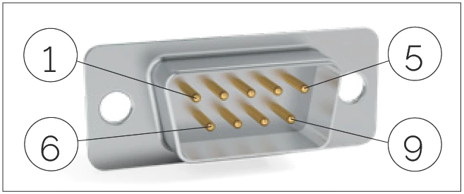
D-Sub 9 connector pin layout
Solder terminal pin layout
| Pin | Analog Signal | Digital Signal | Description |
|---|---|---|---|
| 1 | Ua1- | A - | Quadrature signal |
| 2 | 0V | 0V | Ground |
| 3 | Ua2- | B - | Quadrature signal |
| 4 | ERR NOT | ERR NOT | Error signal (Low = Error) |
| 5 | Ua0 - | R - | Reference signal |
| 6 | Ua1 + | A + | Quadrature signal |
| 7 | + 5V DC | + 5V DC | Supply voltage |
| 8 | Ua2 + | B + | Quadrature signal |
| 9 | Ua0 + | R + | Reference signal |
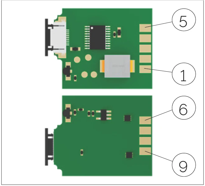
Male 10-pin Micro Match connector:
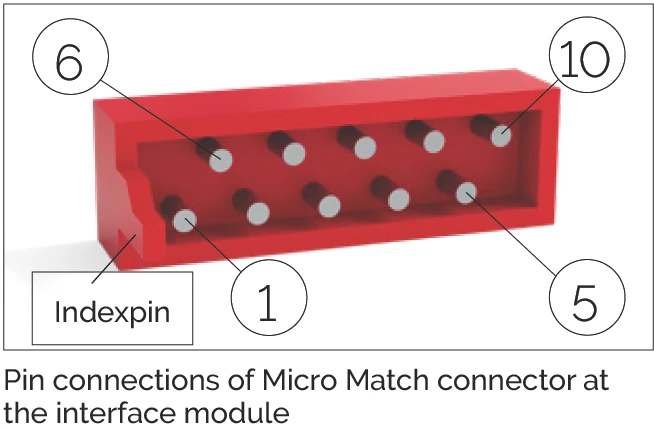
Micro Match 10P connector pin layout
| Pin | Analog Signal | Digital Signal | Description |
|---|---|---|---|
| 1 | nc | nc | |
| 2 | Ua1 + | A + | Quadrature signal |
| 3 | + 5V DC | + 5V DC | Supply voltage |
| 4 | Ua2 + | B + | Quadrature signal |
| 5 | Ua0 + | R + | Reference signal |
| 6 | Ua1 - | A - | Quadrature signal |
| 7 | 0V | 0V | Ground |
| 8 | Ua2 - | B - | Quadrature signal |
| 9 | ERR NOT | ERR NOT | Error signal (Low = Error) |
| 10 | Ua0 - | R - | Reference signal |
5.2.2 Sensor print
Note: This information is only relevant for customers that process the raw signals directly and therefore do not use the available interface module.
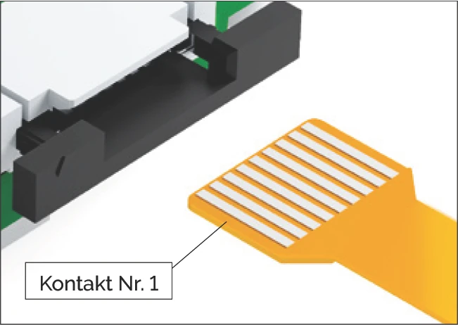
Pin connection of the flexible sensor print
| Pin | Signal | Description |
|---|---|---|
| 1 | PZ | Raw signal reference |
| 2 | GND | Ground |
| 3 | NZ | Raw signal reference |
| 4 | +5V DC | Supply voltage |
| 5 | Diode | Supply of lighting |
| 6 | PSIN | Raw signal sine |
| 7 | NSIN | Raw signal sine |
| 8 | PCOS | Raw signal cosine |
| 9 | NCOS | Raw signal cosine |
5.3 Controller
The MINISCALE PLUS is compatible with every controller that has an incremental encoder port for 1 Vpp signals (analog sine/cosine) or an RS-422 port (digital TTL). The MINISCALE PLUS can be connected to RS-422 or RS-485 encoder inputs.
Suitable modules are available from leading controller manufacturers, including Siemens, Beckhoff, ACS, etc.
For simple applications, a USB counter (for example from Heilig & Schwab; see product catalog Section 5.2) can be used to connect the MINISCALE PLUS directly to a PC.
The maximum input frequency must be considered when selecting a controller. Frequencies up to 8 MHz may occur, depending on the travelling speed and the resolution. See Section 6.4 for some calculated examples.
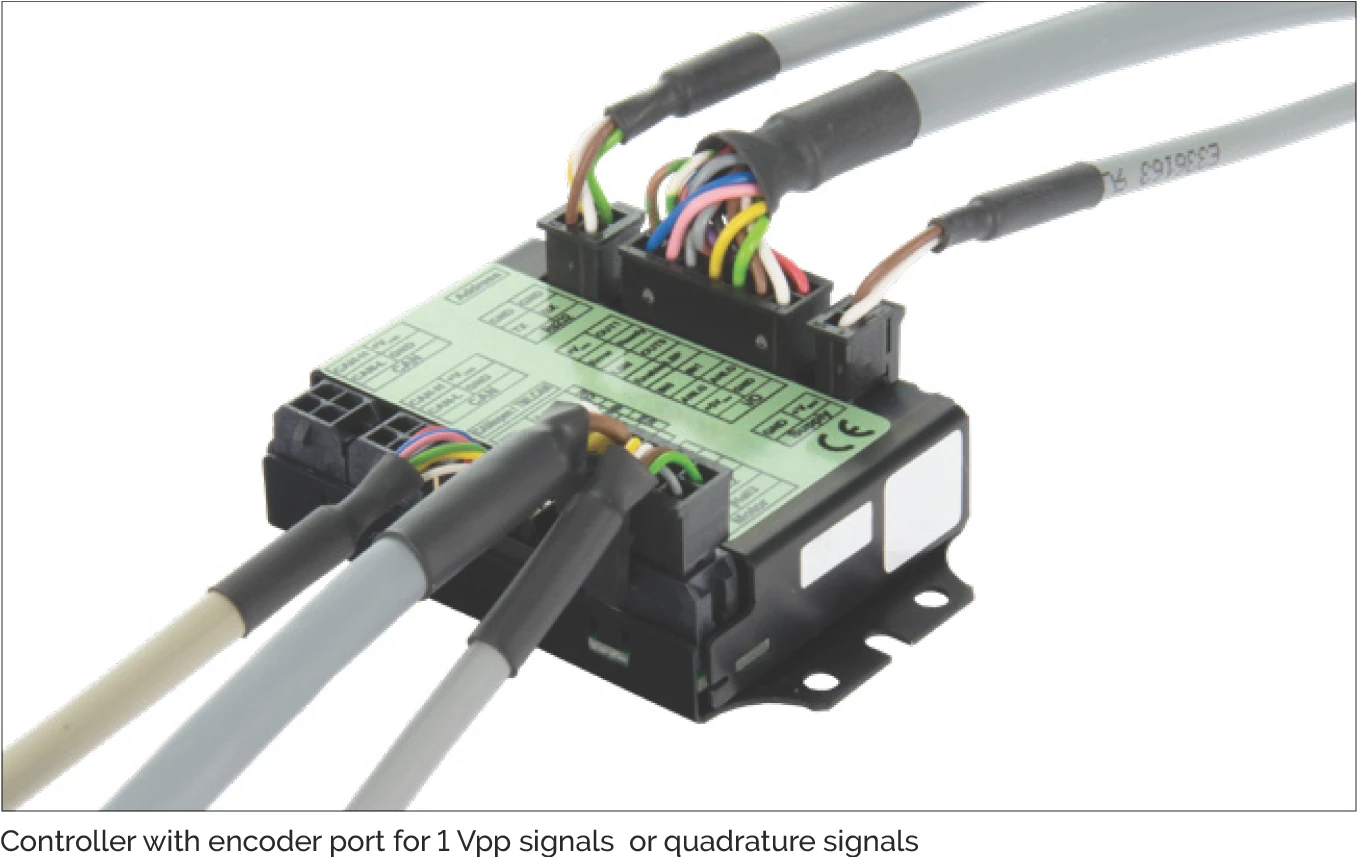
Controller with 1 Vpp signal or quadrature signal encoder port
5.3.1 Settings
For analog signals
The analog signal must be interpolated in the customer-provided equipment in order to obtain the appropriate resolution. The signal period corresponds to a distance of 100 μm.
Example: Signal period 100 μm, interpolation factor 250 and four-edge evaluation yields 0.1 μm resolution.
For digital signals
The step size in the drive controller must be configured according to the selected resolution and type of edge evaluation.
The standard resolution of the MINISCALE PLUS is 0.1 μm. A resolution of 1 μm or 10 μm can be ordered as an option.
Most controllers allow selection of the type of edge evaluation. The choices are four-edge, two-edge and single edge evaluation (see Section 6.3).
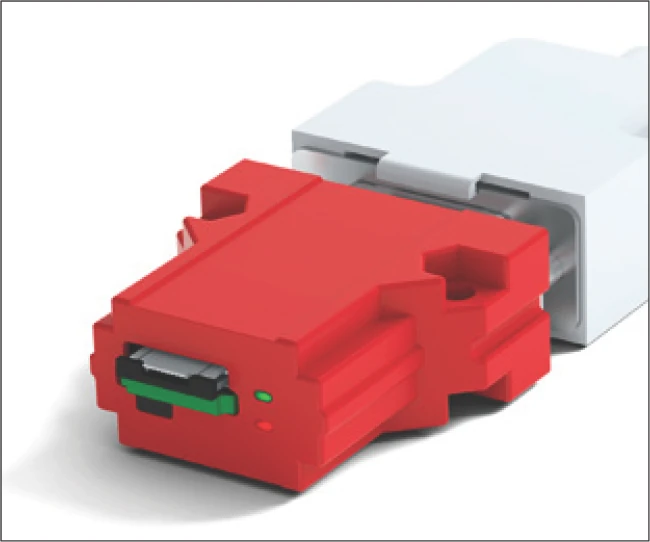
5.4 Function Check
The green LED will light up if the MINISCALE PLUS is correctly supplied with power.
Interface module without MINISCALE PLUS flexible sensor print. Both the green and red LEDs light up.
Interface module with correctly connected MINISCALE PLUS flexible sensor print. The green LED lights up.
If the carriage is on the guideway and the LED lights up red despite the flexible sensor print being inserted, the error should be found using the table in chapter 9.2 "Error Description".
| LED | Supply missing | Supply connected, normal operation | Error condition |
|---|---|---|---|
| Red | does not light up | does not light up | lights up red |
| Green | does not light up | lights up green | lights up green |
The status of the interface module is shown electronically with the output ("ERR NOT"). ERR NOT is a 5-volt output (TTL level), where a "low - signal" = "pending error" and a "high - signal" = "no error".
The Error signal should be connected to a high-impedance input. If the input impedance is too low, a current will flow through the red LED and cause it to glow.
6 Technical Principles
6.1 Performance Parameters of MINISCALE PLUS
| Max. acceleration | 300 m/s² |
| Max. speed | 5 m/s (analog), 3.2 m/s (digital) |
| Preload classes | V1 Preload 0 to 0.03 C (C = dynamic load capacity) |
| Accuracy classes | G1 |
| Materials | |
| - guideways, carriages, ball bearings | Stainless, through-hardened steel |
| - ball recirculation | POM |
| Areas of application | |
| - temperature range (1) | -40 °C to +80 °C (-40 °F to +176 °F) |
| - vacuum | On request |
| - humidity | 10 % to 70 % (non-condensing) |
| - cleanroom | Cleanroom class ISO 7 or ISO 6 (in accordance with ISO 14644-1) |
| Resolution | TTL output 0.1 μm (3) (optional: 1 μm / 10 μm) |
| Accuracy (2) | 1000 mm ± 5 μm (4) |
| Repeatability (2) | Unidirectional ± 0.1 μm Bidirectional ± 0.2 μm (with resolution of 0.1 μm) |
| Dimensional scale | Pitch 100 μm, Max. length 1000 mm Coefficient of expansion 11.7 × 10⁻⁶ K-1 |
| Supply voltage | 5 V DC ± 5 % |
| Current consumption (typical) | 60 mA (analog) / 90 mA (digital) |
| Output signal | Analog: 1 Vpp (at 120 Ω) Digital: TTL in accordance with RS 422 standard |
| Source format | Differential sin/cos analog signals with reference pulse, or Differential, interpolated digital signals (A, B, R) The reference signal is synchronised with the incremental signals |
(1) The standard lubrication covers a temperature range from -20 °C to +80 °C. Lubricants for other temperatures are available upon request from SCHNEEBERGER.
(2) The values apply to a room temperature of 20 °C (68 °F).
(3) Note the high signal frequencies at high resolution and high speed.
(4) Linearity protocol available on request.
6.2 System Accuracy
6.2.1 System accuracy
The system accuracy consists of the long-wave deviation (linearity of the dimensional scale) and the short-wave deviation (e.g. interpolation accuracy) of the scanning system (sensor and interface module). The accuracy values refer to a room temperature of 20 °C (68 °F).
Long-wave deviation
The linearity of the dimensional scale refers to the entire rail length. At this length, the deviation of the dimensional scale is always less than ± 5 μm at an ideal scale.
Short-wave deviation
All incremental distance measuring systems are influenced by the effects of periodic deviation. This periodic deviation, also called short-wave deviation, occurs due to small deviations in the sensor system or electrical signal processing. This means that the sine and cosine signals deviate from the mathematically exact form. If periodic deviations only occur during digitization and calculation of position, then we talk about an interpolation error.
The short-wave deviation of MINISCALE PLUS is always within a range of ± 0.6 μm.
The linearity of the dimensional scale is recorded for each system and can be provided to the customer on request. The record always refers to a specific guideway (see the rail number).
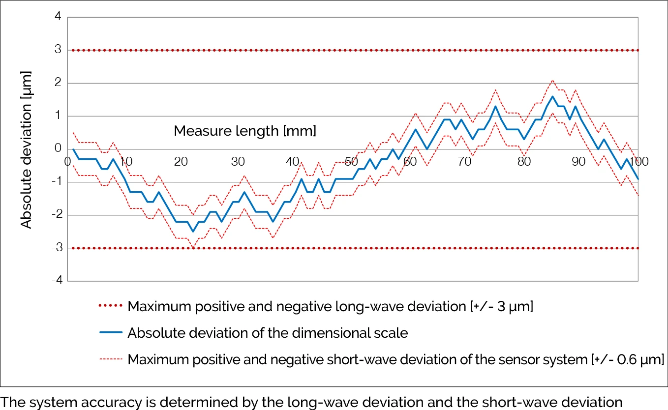
The system accuracy is determined by long-wave deviation and short-wave deviation.
Red dashed line (thick): Max. positive/negative long-wave deviation [+/- 3 μm]
Blue solid line: Absolute deviation of the dimensional scale
Red dashed line (thin): Max. positive/negative short-wave deviation of the sensor system [+/- 0.6 μm]
6.3 Interpolation
For distance measuring applications, interpolation means the signal conversion of analog input signals into digital output signals with a smaller signal period. This is necessary as counter readings and/or position readings cannot be generated directly from analog signals.
The interpolation factor defines the ratio of signal periods from the analog input signal to the digital output signal.
The output of the interpolation process is a quadrature signal, which means two pulse waveforms with a 90° phase offset. The resolution is defined by the distance between two edges of the quadrature signal.
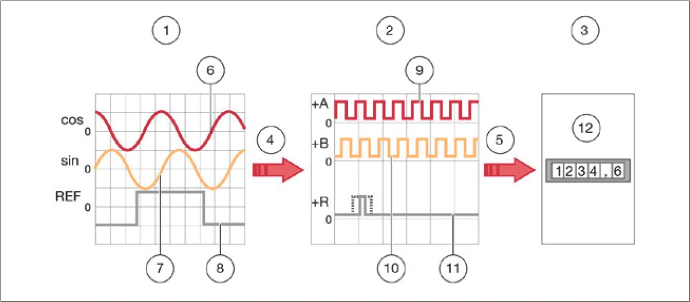
The analog input signals (sin, cos, REF) are interpolated (red arrow) to digital output signals (+A, +B, +R). Inverted signals (-A, -B, -R) not shown.
1. Analog input signal: sin, cos, REF
2. Digital output signal: +A, +B, +Z
3. Downstream electronics
4. Interpolation
5. Signal transmission
6. Analog input signal (cos)
7. Analog input signal (sin)
8. Analog input signal (REF)
9. Digital output signal (+A)
10. Digital output signal (+B)
11. Digital output signal (+Z)
12. Measuring counter, PC, machine controller etc.
6.4 Evaluation of Digital Signals
The digital signals, consisting of the two incremental signals A and B and the reference signal R, are transmitted to the downstream electronics. This can be a simple display unit, a PC or a machine controller.
The downstream electronics determines the position value from the digital signals by counting the signal edges. The counting direction is determined from the phase relationship of the signals A and B. Depending on how many edges are being evaluated, we talk about:
1. Single edge evaluation
Only one edge is counted per channel. One measuring step will therefore correspond to one digital signal period.
2. Two-edge evaluation
Both rising and falling edges of a channel are counted. One measuring step will therefore correspond to half the digital signal period.
3. Four-edge evaluation
Both rising and falling edges of both channels are counted. One measuring step will therefore correspond to a quarter of the digital signal period.

1. Single edge evaluation 2. Two-edge evaluation 3. Four-edge evaluation
4. In each case one measuring step 5. Resolution 6. Digital signal period
6.4.1 Resolution
The resolution is the smallest measurable change in position of the measuring system. This corresponds to the distance between two edges of the quadrature signal. The resolution is determined by the period of the analog signal, the interpolation factor and the evaluation method.
Example of resolution calculation (A)
| I Interpolation factor (default) | 250 |
| P Period of the input signal | 100 μm |
| E Evaluation (4 edges) | factor = 4 |
A = PI × E = 100 μm250 × 4 = 0.1 μm
6.5 Signal Frequency
The signal frequency at the interface module output depends on the travelling speed and the resolution (digital module) or the increment of the dimensional scale (analog module). To ensure that no steps are lost, the maximum input frequency of the controller must be greater than the calculated maximum output frequency of the interface module.
f = vP
f = Frequency (Hz) v = Speed (m/s) P = Increment (m)
6.5.1 Example of calculation for analog MINISCALE PLUS
| v travelling speed | 2 m/s |
| P signal period (corresponds to the increment of the dimensional scale) | 100 μm |
f = vP = 2 m/s100 × 10-6 m = 20,000 Hz = 20 kHz
6.5.2 Example of calculation for digital MINISCALE PLUS
The maximum output frequency of the digital interface module is 8 MHz per channel. This means that the A signal and B signal can each have a maximum frequency of 8 MHz. With four-edge evaluation of the A/B signals, the counting rate is 32 MHz, corresponding to a maximum speed of 3.2 m/s with a resolution of 0.1 μm.
Maximum performance of digital MINISCALE PLUS
| v max. speed | 3.2 m/s |
| A Resolution | 0.1 μm |
| P Digital signal period (4 × resolution) | 0.4 μm |
Calculation of the maximum output frequency of the interface module, which corresponds to the minimum required input frequency range of the controller:
f = vP = 3.2 m/s0.4 × 10-6 m = 8,000,000 Hz = 8 MHz
Calculation of the minimum required controller counting frequency (with 4-edge evaluation):
fcount = vA = 3.2 m/s0.1 × 10-6 m = 32,000,000 Hz = 32 MHz
Example speed v
In the opposite direction, the speed or resolution can be calculated from a given frequency (for example, limited by the selected controller).
| f max. controller input frequency | 1 MHz |
| A Resolution | 0.1 μm |
| P Digital signal period (4 × resolution) | 0.4 μm |
Vmax = f × P = 1 MHz × 0.4 μm = 0.4 m/s