1. About These Installation Instructions
1.1 Function and Application
The gear rack installation instructions describe how the gear rack drive components are fitted.
1.2 Target Group
SCHNEEBERGER has defined the following user groups:
- Machine builder
- Machine end user
The machine builder is SCHNEEBERGER's direct customer. They fit the SCHNEEBERGER component into their machine and sell the end product to end user. These installation instructions are intended for machine builders.
1.3 Additional Literature
Dimensions and other details about the gear racks are in the gear rack catalogue: www.schneeberger.com/en/
2. For Your Safety
2.1 Authorised Staff
2.2 Intended Use
SCHNEEBERGER gear racks are components for precise linear movements. Please note the following limits:
- Operating temperature range: -40°C to +80°C
- SCHNEEBERGER gear racks must not be used as safety components
2.3 General Safety and Protective Measures
| Item | Description |
|---|---|
| Storage | Store gear racks in their original packaging and protect them from damp and damage |
| Fitting | When fitting, all components must be kept at the same room temperature |
| Repairs | Only use original SCHNEEBERGER parts for repairs |
| Miscellaneous | Comply with country-specific regulations, standards and guidelines for accident prevention. To ensure that the products work properly, also observe the instructions on profile and location tolerances, lubrication and environmental conditions |
2.4 Environmentally Responsible Behaviour
Do not allow lubricants to end up in the environment and dispose of in accordance with country-specific regulations.
3. Description
3.1 Basic Points
Gear rack drives' main feature is their high level of efficiency. They are the best choice for high axial forces. This drive rigidity is constant over the whole length. They are also very cost effective for long strokes of more than 2 m.
With a rack and pinion system a slideway is driven by the pinion running on a fixed gear rack. There is a basic difference between straight and helical toothed gear racks. Apart from typical dimensions, SCHNEEBERGER supplies any cross sections with metric or module pitches. The maximum one-piece length is 3000 mm. This means that they can be joined in any sequence.
The tooth rack can be milled or ground depending on the customer's requirements. A particular feature is that different materials and hardening processes can be used. Depending on the load to be applied you have a choice of:
- Soft gear racks
- Induction hardened gear racks
- Case-hardened gear racks
- Nitride hardened gear racks
3.2 Components
The gear racks are described in detail by the order description. Further details are contained in the associated drawing.
4. Storage and Transport
When dispatched, gear racks are protected from corrosion and should not be stored in their original packaging for more than a year. Gear racks must be stored in dry, heated storerooms.
You must bear the following points in mind when transporting:
- Transport in the original packaging
- Bending effects must be avoided with long gear racks
- Protect from impacts and moisture
5. Preparation for Installation
5.1 Cleaning
The machine and supporting surfaces should be degreased, cleaned and prepared with an oil stone. When they are supplied the gear racks already have corrosion protection. This must be removed immediately before fitting. They should be fitted in a clean, dry environment because dirt will have a detrimental effect on their operation.
The mounting surfaces of the slideway must be thoroughly cleaned and then prepared with an oil stone.
The grease must not be removed from the tapped fixing holes in the machine bed because otherwise the friction when tightening will be too great and the screw's required preload force will not be reached. In this case apply a little oil.
After cleaning, the gear racks must be placed on the machine bed so that the temperatures can adjust.
5.2 Tools and Aids Required
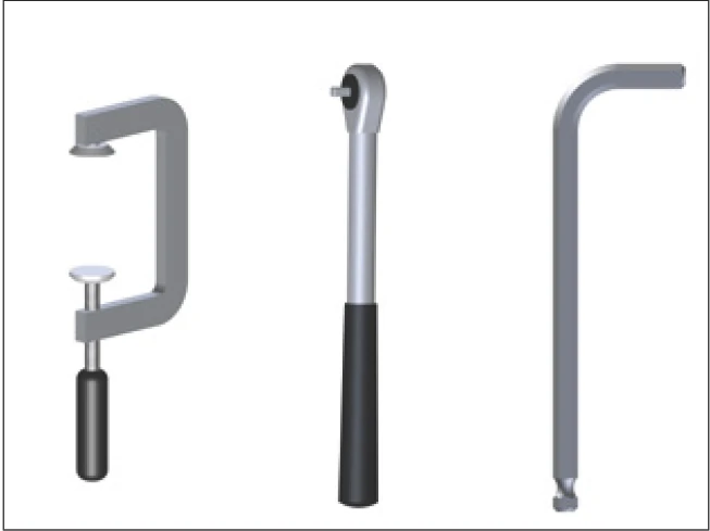
Installation tools: screw clamp, torque wrench, hex key
- Personal protective equipment, protective gloves
- Torque wrench
- Fixing screws
- Oil stone
- Cleaning cloths
- Screw clamps
- Modules and angled mounting plate
A lifting device may sometimes be necessary to fit the gear racks. You must ensure that suitable tools/equipment is available. Cylinder screws and dowel pins are required for fixing the gear racks, as described in the table below:
Screw and Dowel Pin Specifications
| Module | Cylinder Screw | Dowel Pin* |
|---|---|---|
| 2 | M6 | 6 m4 |
| 3 | M8 | 8 m5 |
| 4 | M8 | 8 m6 |
| 5 | M12 | 12 m8 |
| 6 | M16 | 16 m8 |
| 8 | M20 | 20 m10 |
| 10 | M30 | 20 m10 |
| 12 | M36 | 20 m10 |
* We recommend dowel pins with an internal thread for ease of removal.
5.3 Checking the Delivery Schedule
The gear racks should be checked for dirt and external damage. Damaged or dirty gear racks must not be installed.