1 Safety Instructions
1.1 Scope of Application
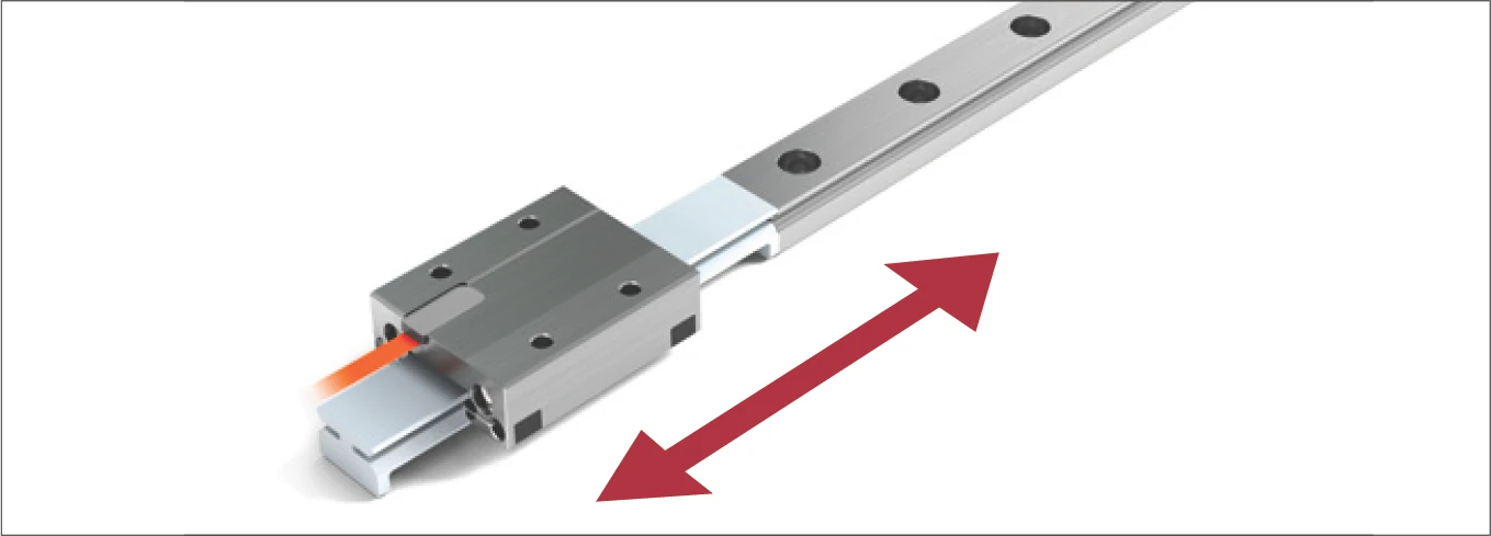
These instructions describe installation of MINISCALE PLUS guideways with integrated measuring system.
Supplementary Literature: MINI-X product catalog.
1.2 Authorized Staff
MINISCALE PLUS guideways must only be assembled by appropriately trained specialists who have read and understood these instructions.
1.3 Intended Use
MINISCALE PLUS guideways can only be exposed to the approved environmental influences (see product catalog).
1.4 General Safety and Protective Measures
ATTENTION!
MINISCALE PLUS is sensitive to electrostatic discharge!
The electronics can be damaged if precautions are not taken against electrostatic discharge (ESD). ESD regulations must therefore be observed when handling ESD-vulnerable parts (EN 100015-1).
- Before working on electrical equipment, switch off or disconnect the power supply and ensure that it cannot be switched on or connected again unintentionally.
- Country-specific regulations, standards and guidelines for accident prevention must be observed.
- Do not store the products outdoors, and protect them against moisture (10% - 70% relative humidity, non-condensing).
- Observe the specified temperature range (-40 °C to +80 °C).
- Only remove the products from their original packaging at their installation location and immediately prior to installation.
- The products are lubricated in the factory. Check the condition of the lubricant (the service life of the lubricant is limited).
Improper handling of the guideways can lead to pre-damage and thus to premature failure.
1.5 Environmental Protection
- Lubricants should be disposed of in an environmentally responsible way.
- Decommissioned components should be disposed of in accordance with local/national laws and guidelines.
1.6 Transport
MINISCALE PLUS are high-precision components and should be handled with care. For transportation of these products in-house, the following points should therefore be noted:
- Transport guideways and accessories in their original packaging.
- Protect guideways against impacts.
2 Configuration of the Base Structure
2.1 General
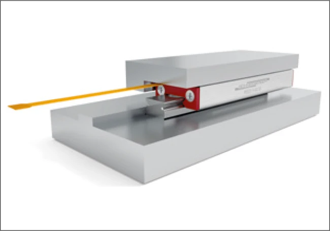
Configuration of the base structure
MINISCALE PLUS guideways are high-precision components. Flatness requirements of the base structure are correspondingly high so that surface inaccuracies are not transferred to the guideways.
MINISCALE PLUS perform best when mounted on a rigid structure with a high level of geometric accuracy. Inaccuracies in the guideway assembly surfaces have a direct impact on their running behaviour, push force, load capacity and service life.
2.2 Surface Quality
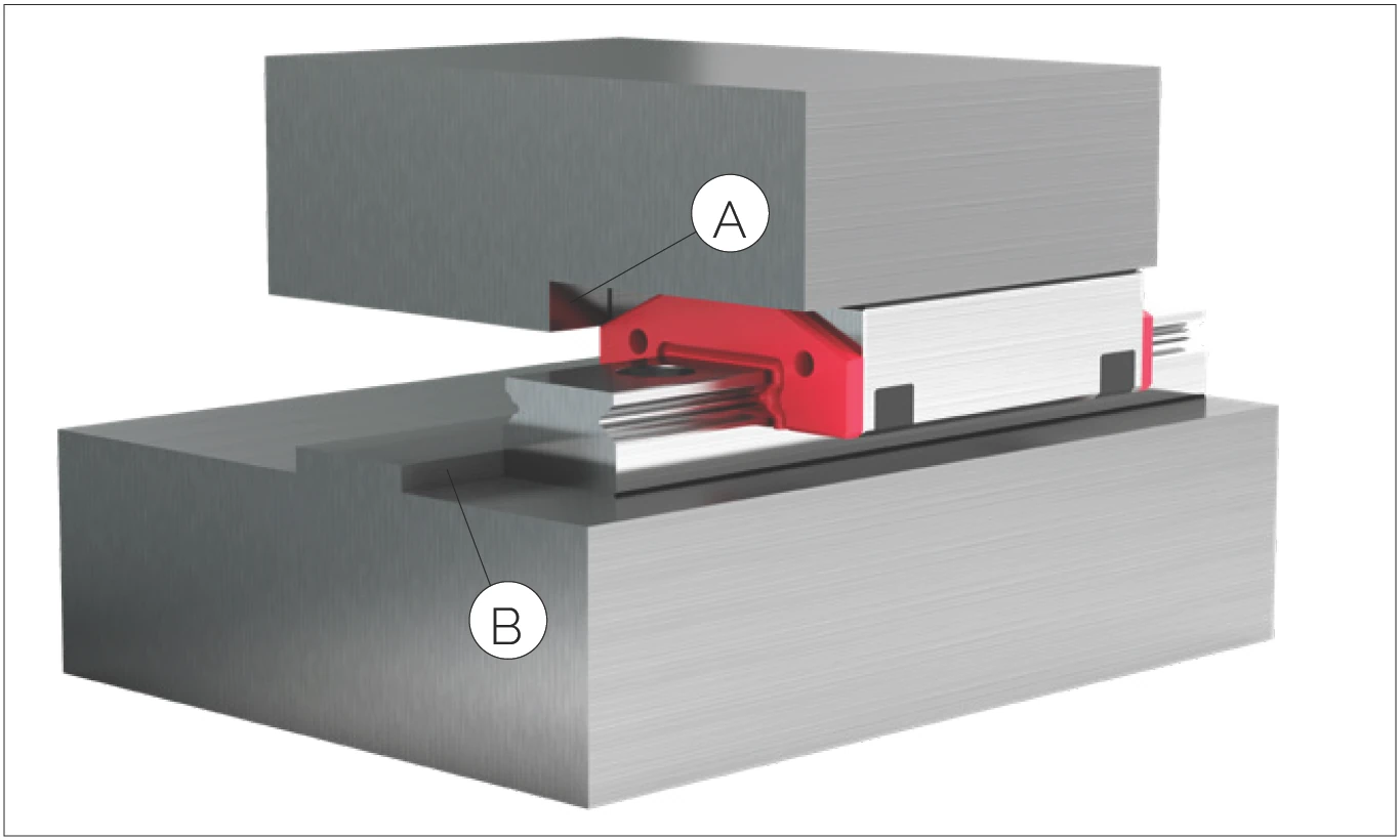
Base structure configuration (A: Carriage, B: Base structure)
The surface quality of the supporting surface does not have a direct influence on the function and running behaviour of the guideway, but it does on the static position accuracy. Carriages and guide rails are compressed against the mounting surfaces by the attachment screws with a high level of force. To prevent relaxation of the assembly, a high surface contact ratio is required. This is achieved by means of high surface quality.
The accuracy of the application critically determines the required surface quality of the supporting and locating surfaces. It is therefore necessary to ensure the following:
- High-precision applications: max. Ra value of 0.4
- Standard applications: max. Ra value of 1.6
2.3 Flatness of the Mounting Surfaces
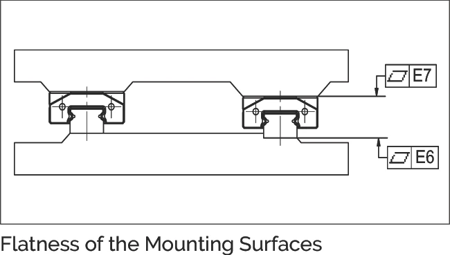
Flatness of the Mounting Surfaces (E7, E6)
For the flatness of the surfaces (E6 and E7), the values in the table below should be targeted.
| Dimensions | Flatness (μm) |
|---|---|
| 7 | 3 |
| 9 | 3 |
| 12 | 4 |
| 15 | 4 |
| 14 | 4 |
| 18 | 4 |
| 24 | 5 |
| 42 | 5 |
2.4 Locating Height and Corner Radii
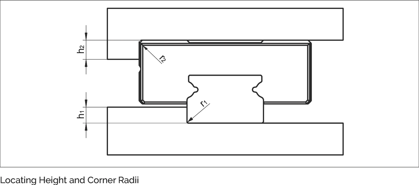
Locating Height and Corner Radii (r1, h1, r2, h2)
Observance of the following height specifications for the locating surfaces guarantees secure absorption of force and sufficient clearance for the carriages.
The locating side of the carriage is opposite the carriage side with the company logo/type designation. The guideway can be located on both sides.
The dimensions listed for the locating surface should be applied to ensure optimal alignment of the guideway and an easy installation.
| Rail width | h1 | r1max | r2max | h2 |
|---|---|---|---|---|
| 7 | 1.2 | 0.2 | 0.3 | 2.5 |
| 9 | 1.5 | 0.3 | 0.4 | 3 |
| 12 | 2.5 | 0.4 | 0.4 | 4 |
| 15 | 3.5 | 0.5 | 0.5 | 5 |
| 14 | 1.8 | 0.2 | 0.4 | 2 |
| 18 | 3 | 0.3 | 0.5 | 3 |
| 24 | 3.5 | 0.4 | 0.5 | 4 |
| 42 | 3.5 | 0.5 | 0.6 | 5 |
2.5 Installation Methods
The load direction and installation complexity must be considered when choosing a suitable installation method and determining the number and arrangement of the lateral locating surfaces.
2.5.1 Load
Tensile and compressive forces do not have any influence on the lateral locating surfaces. If lateral loads exceeding the permissible lateral force are present, locating surfaces must be provided.
The locating surfaces should be arranged according to the force direction of the main load. Lateral locating surfaces should also be provided when vibration and shock loads are present. They also increase the rigidity of the system.
2.5.2 Installation complexity
Locating surfaces simplify installation and reduce the effort necessary for aligning the guide rails. With careful manual alignment of the guideway, lateral locating surfaces are not essential. When deciding on a method, installation complexity should be carefully weighed against design and manufacturing complexity.
2.5.3 Installation options
Shown below are some typical installation methods that differ in terms of the number and orientation of the locating surfaces, the lateral force capacity and the installation complexity. These examples are intended to serve as a design aid.
Installation option 1
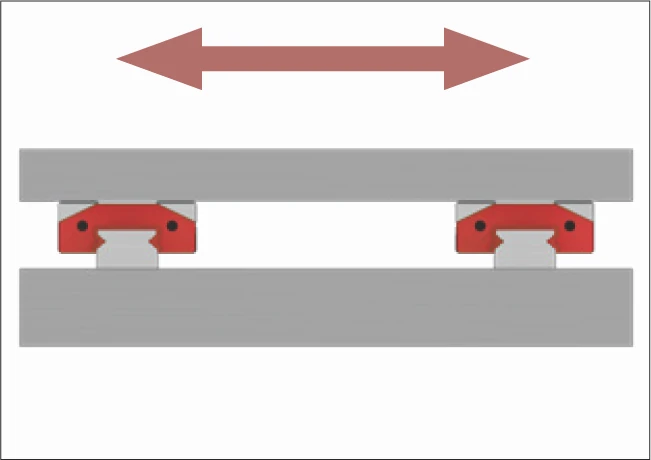
- No reference surfaces
- The forces are transferred by friction locking
- Long installation time and high engineering expense
Installation option 2
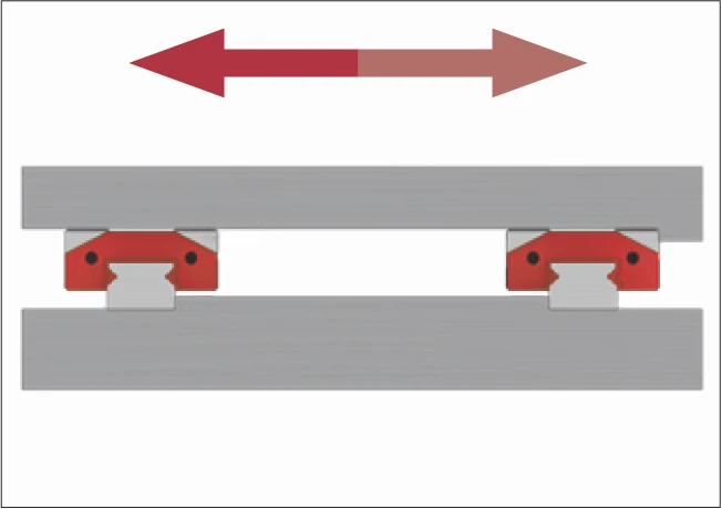
- Both guide rails with one reference. Carriage side with opposite reference
- Simple installation
- High lateral force absorption from one direction, e.g. for hanging installation
Installation option 3
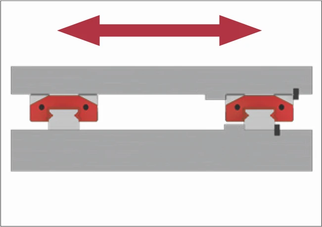
- A guide rail and carriage with reference and lateral clamping
- For high lateral forces from both directions (a guide rail with carriage will take the majority of the lateral force)
- Relatively simple installation