7 Terms and Definitions
7.1 Interface Module
In the interface module, the sensor data is converted into standardized analog signals (1 Vpp) or standardized digital signals (TTL).
- The signals are amplified
- Phase errors between the sine and cosine signals are corrected
- The offset is compensated
The digital interface module also includes an interpolator that converts the analog signals into digital signals. For more information, see Section 6.2, "Interpolation".
7.1.1 Comparison of analog and digital interface modules
| Digital (D) | Analog (A) | |
|---|---|---|
| Advantages |
|
|
| Disadvantages | Very high frequencies at high speeds and high resolution | Realignment at the customer site is not possible, which means that the entire system (guideway and interface module) must be replaced in the event of a defect |
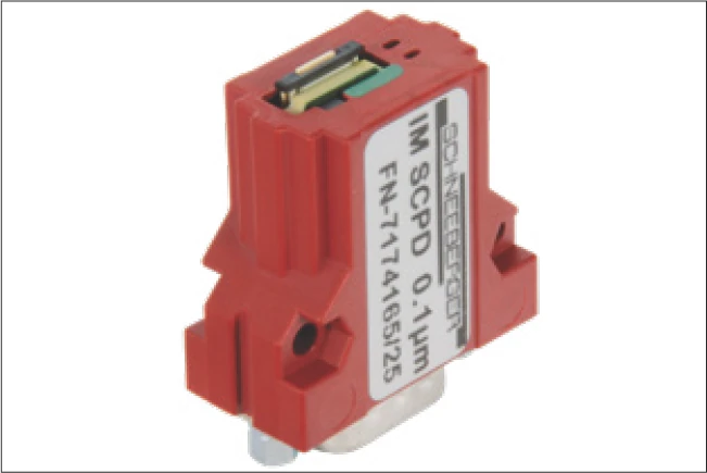
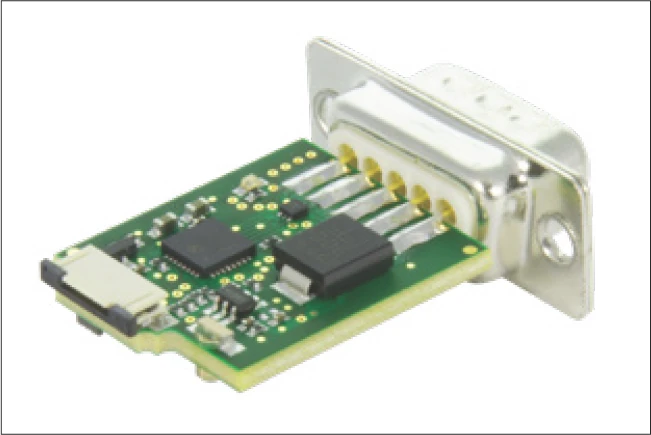
Digital, with housing
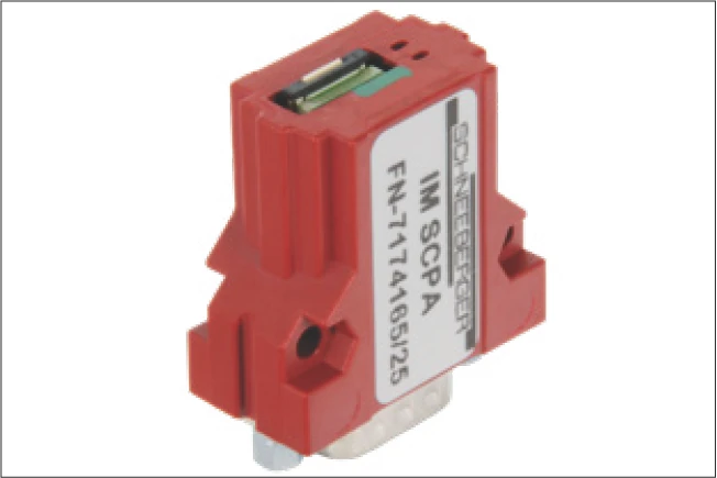
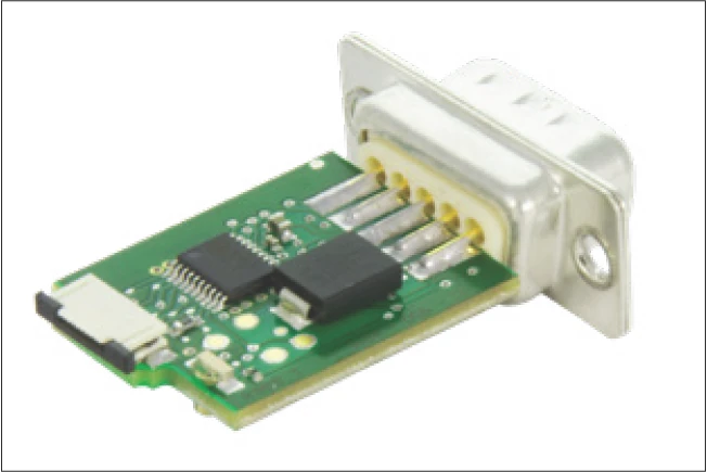
Analog, with housing
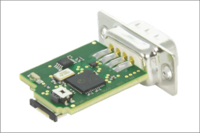
Top view: Digital, without housing
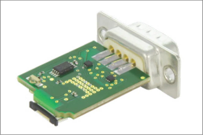
Top view: Analog, without housing
Bottom view: Digital, without housing
Bottom view: Analog, without housing
7.2 Accuracy Class
The accuracy class specifies the maximum expected measuring deviation of a system under the specified operating conditions. A distance measuring system with an accuracy class of 3 μm allows deviations of +/- 3 μm.
7.3 Repeatability
Unidirectional repeatability of a measuring system is generally understood to mean the ability to repeat the results that a particular system returns under exactly the same environmental conditions. In assessing this, the measuring deviation must be known and be factored into the analysis.
The repeatability of an axis position can be determined for a specific travelling speed using simple methods by calculating the arithmetic mean and the standard deviation of many measurements.
7.4 Referencing
Incremental measuring systems cannot determine the exact position after being switched on. For this reason, another track is added alongside the incremental track; the reference track. One or multiple reference points can be marked on the reference track.
A reference run of the carriage is required to reference the system. The axis usually travels in one direction until a mechanical stop. From there, the axis travels backwards until the reference mark is covered. Usually, the equidistant reference mark is always approached from the same direction. (unidirectional)
The controller can then modify the internal counter to a specified value using the reference signal. For the analog interface module, the controller recognizes a predefined position for the incremental signals (this is usually SIN = COS and both greater than zero), as well as REF = "high" as the reference position.
7.5 Periodic Deviations
All incremental distance measuring systems are influenced by the effects of periodic deviation, whose wave length corresponds exactly to the graduation spacing or a fraction of it. This periodic deviation, also called short-wave deviation (SWD), occurs due to small deviations in the sensor system or electrical signal processing. This means that the sine and cosine signals deviate from the mathematically exact form. Deviations can be classified depending on the arrangement (harmonics).
| SWD period | Deviation occurs due to |
|---|---|
| 1 signal period | Sine/cosine offset |
| 1/2 signal period | Sine and cosine amplitude are different |
| 1/3 - 1/8 signal period | Sensors deliver a signal which is fundamentally different from the sine wave shape |
7.5.1 Interpolation Errors
If periodic deviations only occur during digitization and calculation of position, then we talk about an interpolation error.
7.6 Comparator Errors
The comparator error, also referred to as the Abbe error, is a systematic deviation which occurs when the axis of the length standards do not coincide with the axis of the distance standards. The causes for the deviation are minute rotary movements in the axis design, which influence the measuring result.
7.7 Sampling Rate
The sampling rate describes the frequency at which the analog signal is sampled per time interval. Usually the time interval is one second, which is why the unit for the sampling rate is Hz. In order to guarantee a complete reproduction of the original signal, the sampling frequency should be at least twice that of the original signal in accordance with the Nyquist-Shannon sampling theorem.
7.8 Single-Ended Signaling
For single-ended signaling, the voltages change relative to a reference potential (electrical ground). This is a simple and convenient way of transferring data, requiring just one wire per signal.
The disadvantage is the relatively high susceptibility to interference. This type of signaling should therefore only be used for short distances and low speeds.
7.9 Differential Signaling
For differential signaling, the signals are described by a voltage difference without reference to electrical ground. Instead of a single signal conductor, a pair of wires is used. One wire carries the signal, and the other carries its inverse. The controller then composes the difference between the two signals into the so-called difference signal (e.g. the A+ and A- signals become A).
Differential signaling is the better solution for most applications as it is more tolerant to interference. Couplings to the signals are almost identical for both wires such that interference is almost eliminated when generating a difference.
The RS422 standard (differential) was specifically developed for larger distances and higher transfer rates.
7.10 Direction of Travel
The direction of travel can be read from the phase relationship of the electrical signals. One signal either leads or lags the other, depending on the direction.
With the digital interface module: If the carriage moves in the direction of the flexprint, the signal on channel A is 90° ahead of channel B. From this the controller recognizes a positive direction of travel, meaning that the counter counts upwards. In the other direction, the signal on channel A is 90° behind channel B. The counter counts downwards.
The counting direction for the analog interface module is reversed.
8 Application Tips
8.1 Operating Conditions for the MINISLIDE MSQscale
The MINISLIDE MSQscale has an open optical measuring system. As with every optical measuring system, contaminants such as dirt impair the operation of the system. It is therefore not recommended to use the MINISLIDE MSQscale in applications where dust, chips, particles or liquids are expected to be present during the process operation. Large scratches or other types of damage to the dimensional scale are equally harmful.
Generally speaking, the MINISLIDE MSQscale is most suitable for use in clean environments. Typically in situations where other optical devices are used or where a clean environment is present.
In this regard, the MINISLIDE MSQscale differs from the AMS distance measuring systems, which are specifically designed for harsher environments.
8.2 EMC Characteristics of the MINISLIDE MSQscale
The MINISLIDE MSQscale and its accessories have been tested according to the EN 61000 standard. The test results confirm that the MINISLIDE MSQscale complies with the requirements of the standard. However, this does not eliminate the possibility of unwanted electromagnetic interference in specific application cases. Compliance with relevant EMC design practice is always necessary.
8.3 Magnetic Effects on the MINISLIDE MSQscale
Static magnetic fields have no effect on the MINISLIDE MSQscale. Induction effects may occur with alternating fields, depending on the cable layout.
9 Troubleshooting
9.1 Aligning the Digital Interface Module
Alignment is only necessary for a subsequent delivery of the digital interface module! Calibration by the customer is not possible for the analog interface module.
Procedure:
- Switch on MINISLIDE MSQscale
- Press and hold the alignment button A
- Move the guideway slowly along the entire stroke length
- Release the alignment button
- Reset MINISLIDE MSQscale (= switch it off and on again)
- Drive the guideway along the entire stroke length and make sure that only the green LED lights up
- If the red LED lights up, the adjustment procedure must be repeated
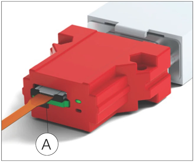
Interface module with housing
A Alignment button
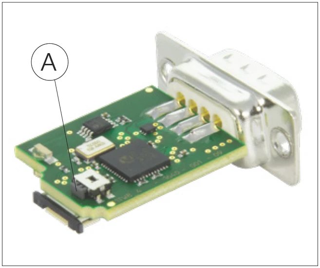
Interface module without housing
A Alignment button
9.2 Error Description
| Error | Possible cause | Solution |
|---|---|---|
| Green LED on interface module not lit | No supply voltage or incorrect supply voltage at interface module | Check supply voltage (+5V DC) |
| Incorrect pin assignment of customer-provided cable | Check pin assignment | |
| D-Sub 9 or Micro Match connector not properly connected | Check connection | |
| The MINISLIDE MSQscale has been damaged by improper handling (not in compliance with ESD requirements) | Replace the MINISLIDE MSQscale | |
| Red LED on interface module lights up | Incorrect supply voltage on interface module | Check supply voltage (+5V DC) |
| Flexible sensor print not connected to interface module | Connect the flexible sensor print | |
| Flexible sensor print not correctly connected to interface module. The contact surface of the flexible sensor print is turned 180° | Turn the flexible sensor print by 180° | |
| The flexible sensor print is not fully inserted in the ZIF connector | Check connection | |
| The flexible sensor print is damaged or kinked (for example, hairline cracks in the contacts) | Replace the MINISLIDE MSQscale | |
| The MINISLIDE MSQscale has been damaged by improper handling (not in compliance with ESD requirements) | Replace the MINISLIDE MSQscale | |
| Sensor input signals outside normal range, for example due to dirty dimensional scale | Clean and coat the dimensional scale as described in Section 3.3. Realignment is possible with a digital system (see Section 9.1) | |
| Red LED glows slightly | "ERR NOT" output connected to a low-impedance input, allowing a small current to flow through the LED | Connect the "ERR NOT" output to a high-impedance input or ignore the glowing LED |
| Position information does not match travel distance | Maximum input frequency of customer's controller exceeded | Reduce travelling speed or resolution |
| Resolution set incorrectly in customer's controller | Adjust settings in customer's controller | |
| Edge evaluation factor too low | Set X4 edge evaluation in customer's controller | |
| Electromagnetic interference | Take EMC protective measures: Use shielded cable with twisted-pair conductors, route motor cables and control cables separately, etc. | |
| The flexible sensor print is damaged or kinked (for example, hairline cracks in the contacts) | Replace the MINISLIDE MSQscale | |
| Position information does not match travel distance (cont.) | Dimensional scale is very dirty | Clean and coat dimensional scale as described in Section 3.3; replace system if necessary |
| Maximum speed of 3.2 m/s exceeded (with 0.1 μm resolution) | Limit the speed to 3.2 m/s or reduce the resolution | |
| Malfunction in digital interface module | The number on the interface module does not match the MINISLIDE MSQscale carriage number | Check matching of interface module and guideway |
| Perform alignment as described in Section 9.1 | ||
| Return system to SCHNEEBERGER | ||
| Malfunction in analog interface module | The number on the interface module does not match the MINISLIDE MSQscale carriage number | Check matching of interface module and guideway |
| Return system to SCHNEEBERGER for alignment | ||
| Reference mark not detected | Reference mark not passed | Adjust travel distance |
| Guideway is dirty | Clean and coat the dimensional scale as described in Section 3.3 | |
| Return system to SCHNEEBERGER | ||
| Incorrect position indication with Heilig & Schwab USB counter | Analog: The interpolator has a fixed interpolation factor of 256, resulting in a resolution of 0.39 μm | Calculate with corresponding resolution |
| The maximum input frequency of the digital input is 500 kHz, so with a resolution of 0.1 μm, the speed is limited to 0.2 m/s (counter 026) or 0.4 m/s (counter 046) | Reduce speed or resolution | |
| Other error | Further investigation needed | Contact SCHNEEBERGER |