4 Installation Guidelines for the Measuring System
4.1 ESD Protection
ATTENTION!
The MINISCALE PLUS optical sensor is an electrostatically vulnerable component and is delivered in ESD-protective packaging (Electrostatic Discharge).
As soon as it is removed from the protective packaging, MINISCALE PLUS and the interface module of the flexible printed circuit board must be protected against electrostatic fields and discharge. As soon as MINISCALE PLUS is assembled and connected ready for use, it is protected from ESD.
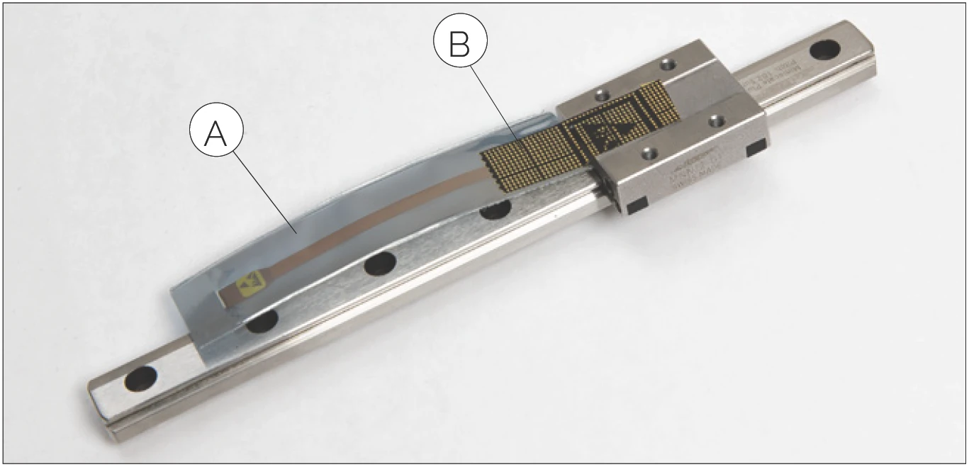
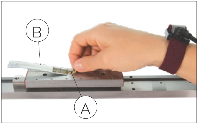
MINISCALE PLUS with ESD Protection
A ESD-protective packaging
B Conductive tape
These installation instructions are not a substitute for ESD training. They only provide an overview of how to handle the MINISCALE PLUS.
For installation of the MINISCALE PLUS guideways, you need at least one ESD wrist strap with a ground lead or crocodile clip for grounding to the machine bed.
ESD protection and/or a wrist strap is not necessary as long as the MINISCALE PLUS flexible sensor print is in the ESD protective packaging.
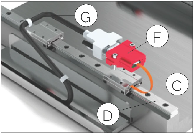
4.2 Overview of Relevant Components
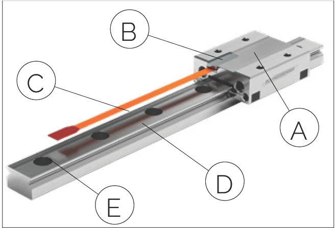
| A | Carriage |
| B | Optical sensor |
| C | Flexible sensor print (must not be exposed to dynamic loads) |
| D | Guideway |
| E | Dimensional scale on the guideway |
| F | Interface module with D-Sub 9 connector |
| G | Control cable (supplied by customer) |
| H | ZIF connector |
4.3 Mating the Interface Module and the Guideway
The rails and carriage of the MINISCALE PLUS guideways are labelled with serial numbers. The number is next to the SCHNEEBERGER logo.
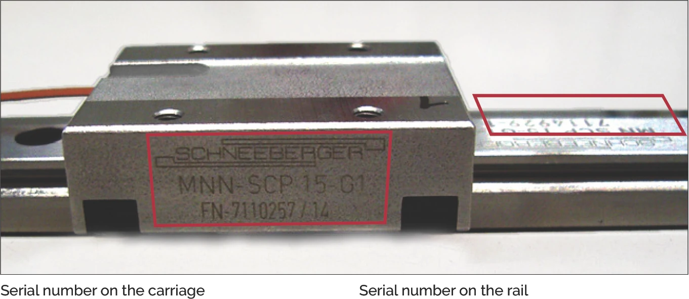
Serial number location on guideway and carriage
The interface modules are configured in factory and matched to the individual MINISCALE PLUS guideways.
Important!
The guideway is supplied as a set or system with the sensor and interface module and must be installed as such.
The carriage serial number is marked on the label of the interface module. This label is attached to the housing or packaging of the interface module.
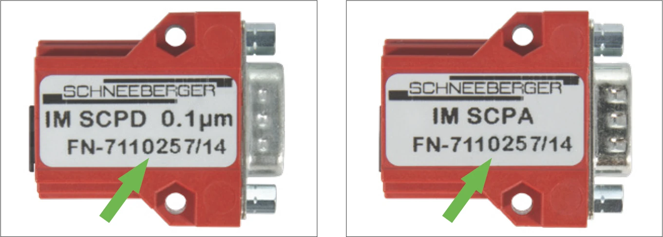
Carriage serial number on the interface module housing label
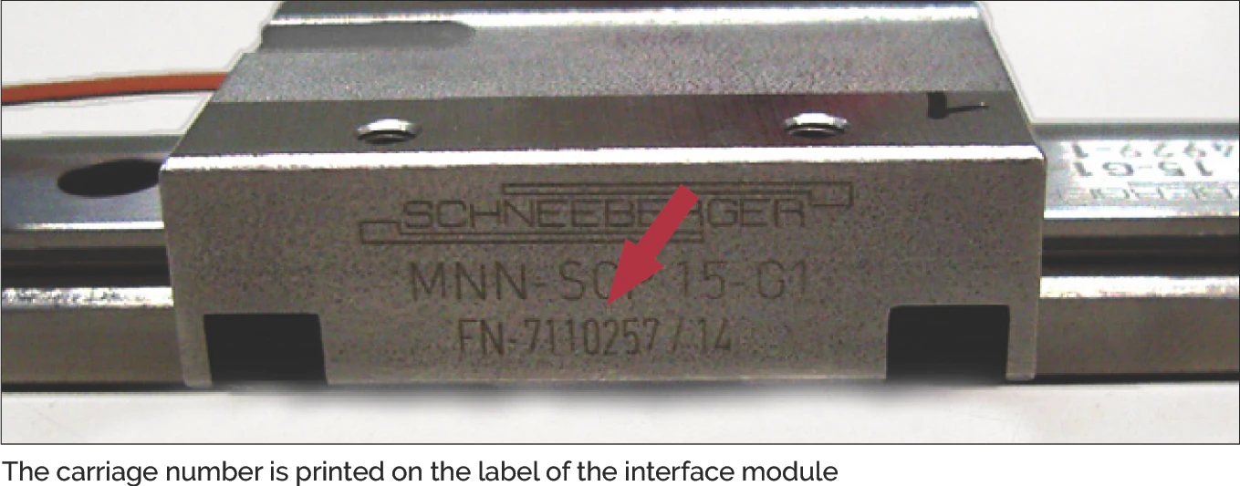
Carriage number printed on the interface module label
4.4 Interface Module Installation Options
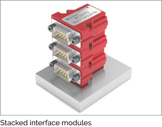
Interface module with housing and D-Sub 9 connector
Advantages:
- Easy screw mounting with M3 screws
- Stackable
- Industry standard connector (D-Sub 9) for customer connection
Interface module without housing, with D-Sub 9 connector
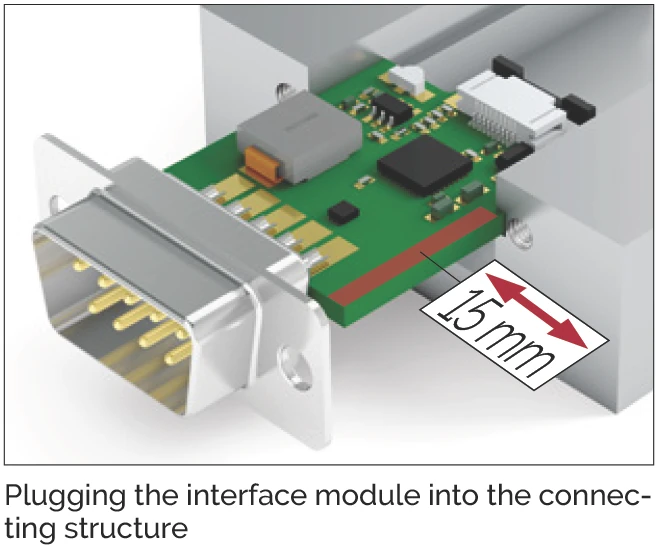
Advantages:
- Board can be clamped on the sides or inserted in guides (board edges allow for 1.5 mm insertion depth)
- More compact due to absence of housing
- Industry standard connector (D-Sub 9) for customer connection
Interface module without housing, with Micro Match connector
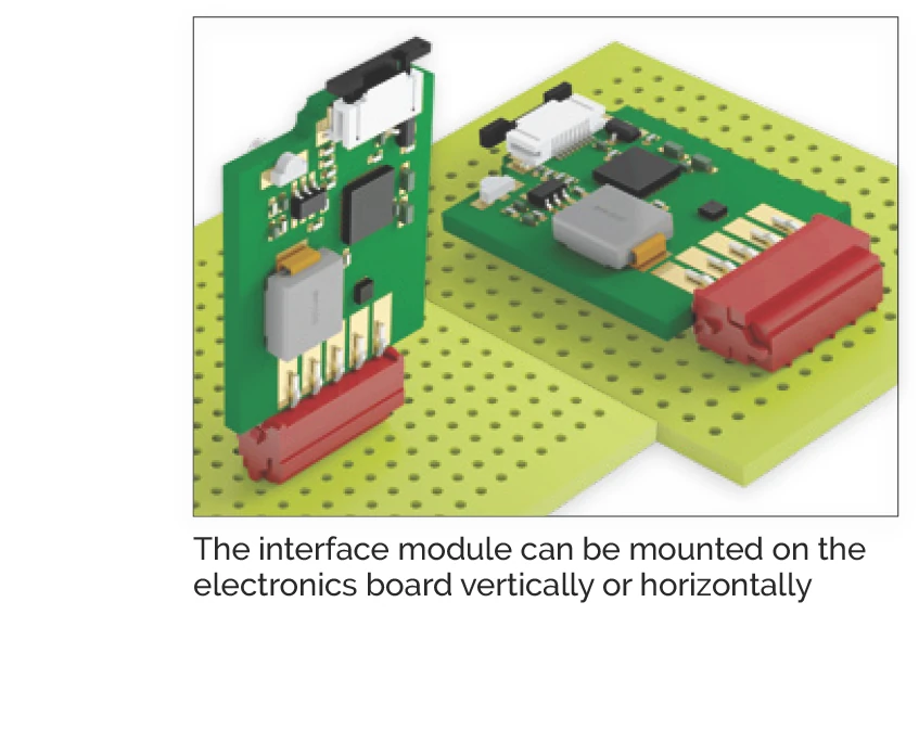
Advantages:
- The board can be plugged into customer-provided electronics with a mating Micro Match connector
Note: The board must be additionally secured for protection against vibration.
Interface module without housing or connector, with solder terminals
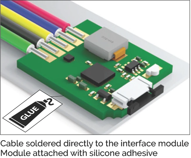
Advantages:
- The board can be clamped on the sides, mounted in guides or secured with an electrically insulating adhesive
- Less room necessary due to absence of housing and connector
- Cable can be soldered directly
- High flexibility for connection design
4.5 Connecting the Flexible Sensor Print to the Interface Module
Always use personal ESD equipment (wrist strap or equivalent) when removing the ESD protection bag.
The ESD-protective packaging should not be removed during installation of the guideway so that the sensor remains protected. The ESD-protective packaging can only be removed once MINISCALE PLUS is grounded on the machine bed and the person is properly protected from ESD (e.g. by wearing a grounded wrist strap).
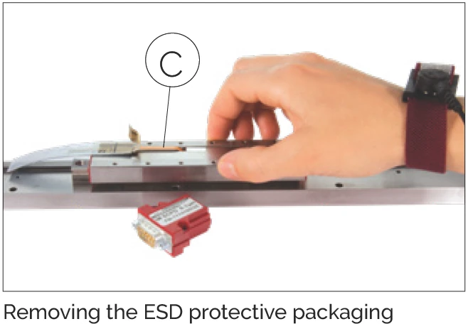
Remove the glue strip A and the ESD protective packaging B.
Be careful to avoid damaging the flexible sensor print C when removing the protective packaging.
Important!
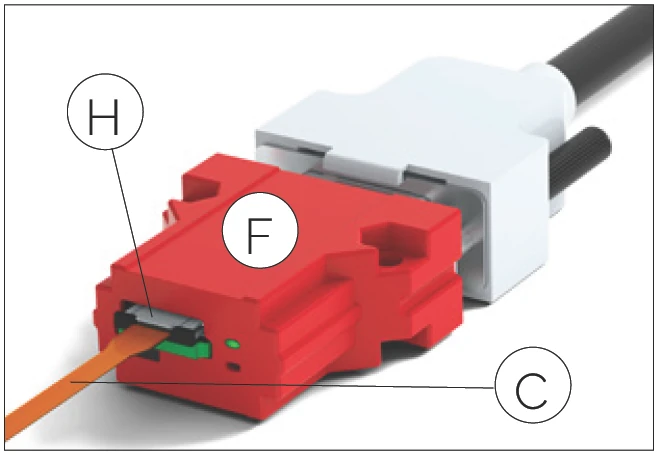
The flexible sensor print is connected to the interface module through a zero insertion force (ZIF) connector.
No force is necessary for insertion. Excessive strain on the ZIF connector can cause the locking mechanism to break. Excessive pressure on the flexible sensor print can cause it to buckle and damage the conducting tracks.
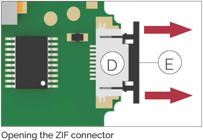
Open the ZIF connector D on the interface module.
To do so, grasp both ends of the black tab E and pull it out approximately 1 mm.
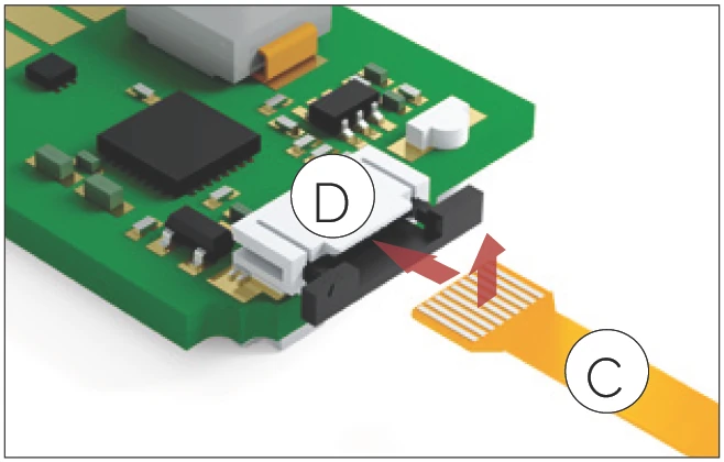
The contact surfaces of the flexible sensor print must face upwards (away from the PCB).
Gently insert the flexible sensor print C approximately 3 mm into the ZIF connector D.
Make sure that the contact surfaces of the flexible sensor print are facing upwards (away from the PCB) to make proper contact.
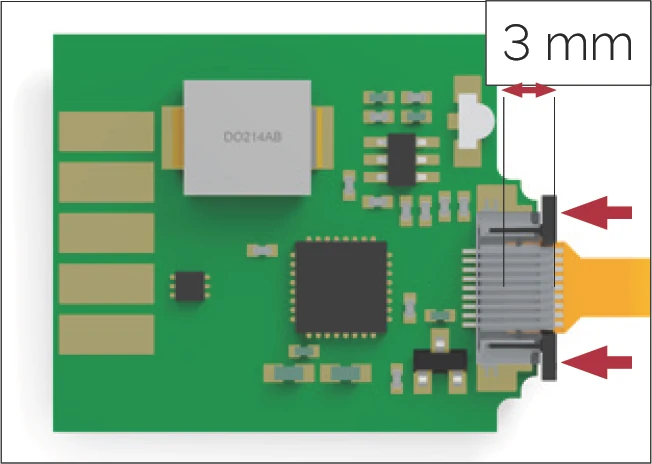
Insert the flexible sensor print about 3 mm into the ZIF connector. Then push the tab back again.
After inserting the flexible sensor print, lock the ZIF connector again by pushing the black tabs toward the PCB.
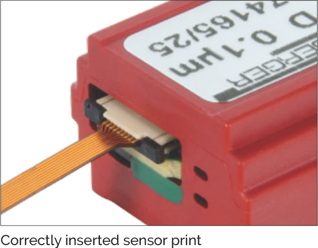
Flexible sensor print correctly inserted and locked
Important!
The flexible sensor print between the sensor and the interface module may only be used statically. The minimum allowable bending radius of the flexible sensor print is 2 mm.
Forcibly pulling out the flexible sensor print can damage the sensor print (the ZIF connector retaining force is only a few newtons).
4.6 Extension Installation (FFC Cable)
The flat flex cable (FFC) is shielded. The shield consists of a metalized film connected to pin 2 (GND). The extension cable must therefore be connected to the adapter board and the interface module with the right orientation. For this, pay attention to the color coding. The metalized shield is covered by an insulation layer to prevent short circuits with other machine parts.
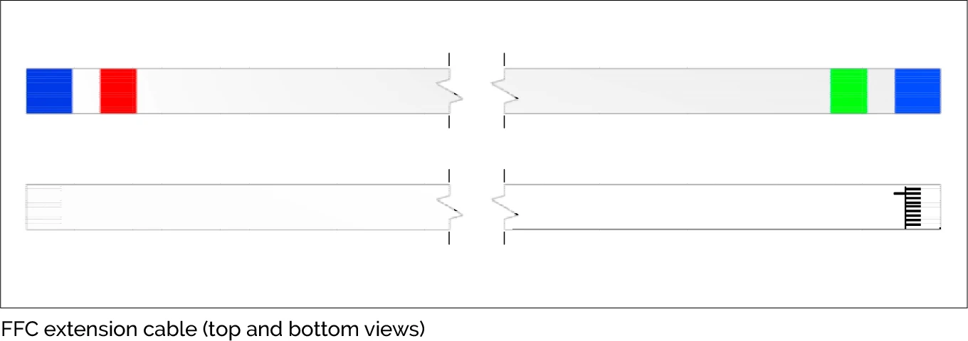
FFC extension cable (top: top view / bottom: bottom view)
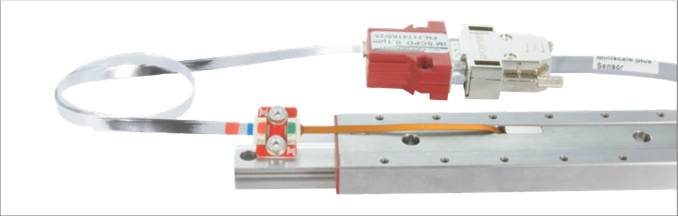
MINISLIDE MSQscale with FFC extension
4.6.1 Color coding
To avoid confusion and mistakes when connecting the individual components, they have specific color coding. When connecting the cable, ensure that the same color is visible on the cable end and the connector.
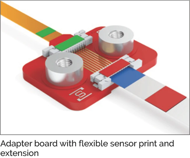
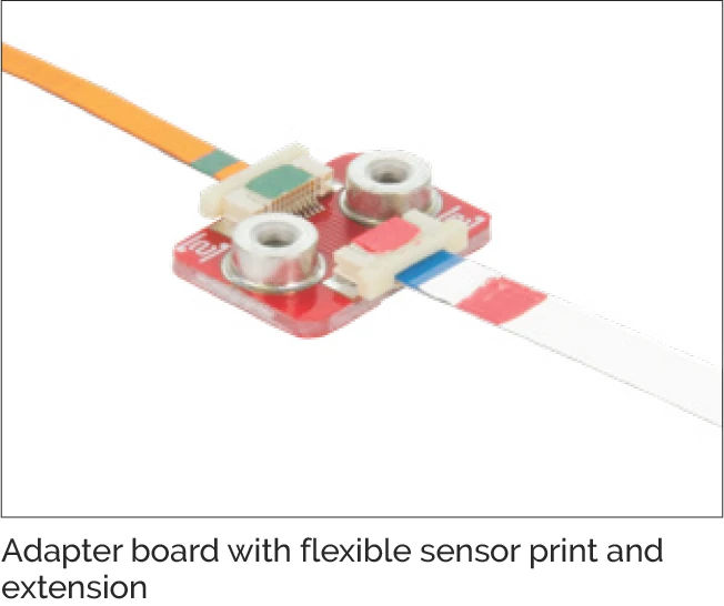
Color coding of the adapter board with flexible sensor print and extension cable
4.6.2 Inserting and locking the cable
When inserting the cable into the ZIF connector, pay attention to the combination of color markings. The green cable end goes to the green ZIF connector. The red cable end goes to the red ZIF connector.
- To unlock the ZIF connector: grasp both ends of the white tab and pull it out 1 mm.
- Gently insert the FFC about 3 mm into the ZIF connector.
- After inserting the flexible sensor print, lock the ZIF connector again by pushing the white tab toward the PCB.
Make sure that the contact surfaces of the flexible sensor print and the FFC are facing downwards (toward the adaptor board) to make proper contact.
4.6.3 Design notes
Minimum bending radius
The recommended minimum bending radius of the FFC cable for dynamic loads is 10 mm.
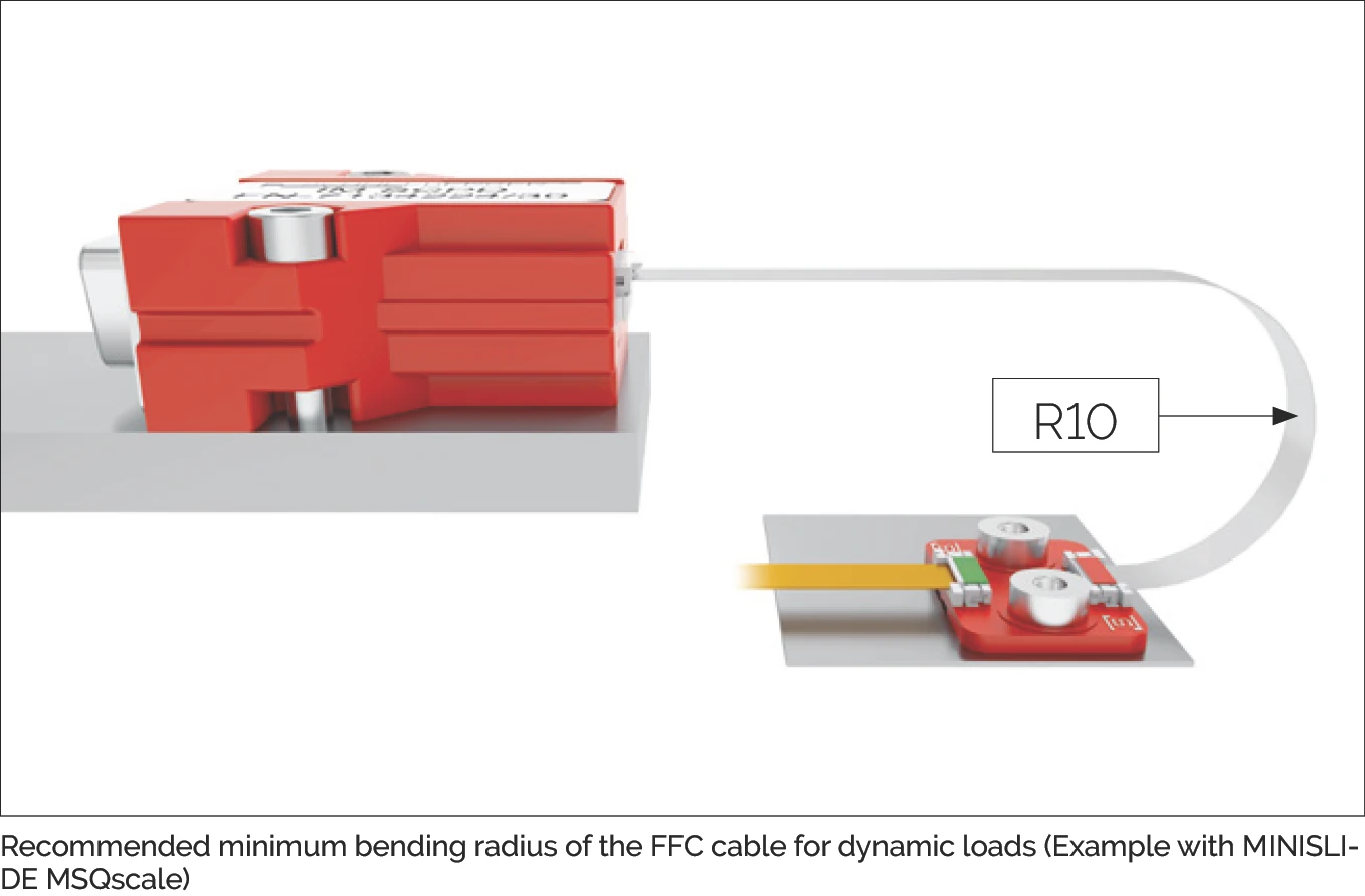
Recommended minimum bending radius for FFC cable under dynamic loads (MINISLIDE MSQscale example)
FFC cable folding
Single folds in the FFC cable are allowed for cable routing. This allows a large degree of design freedom.
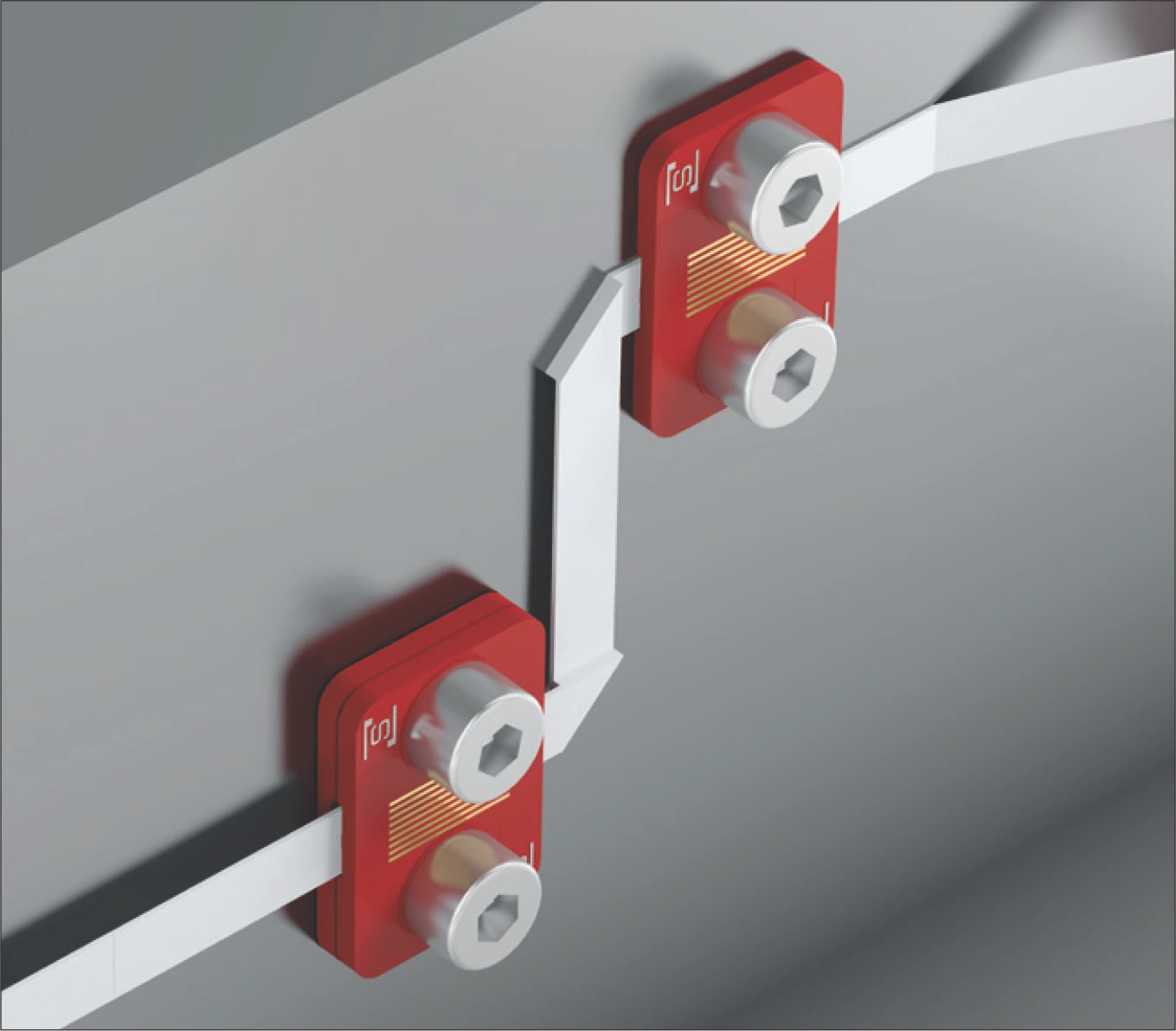
Folded FFC extension cable
Strain relief
- Rear mounting: with an M3 screw threaded into the internal M3 thread of the spacer.
- Front mounting: with an M2 screw threaded into an M2 threaded hole in the substructure.
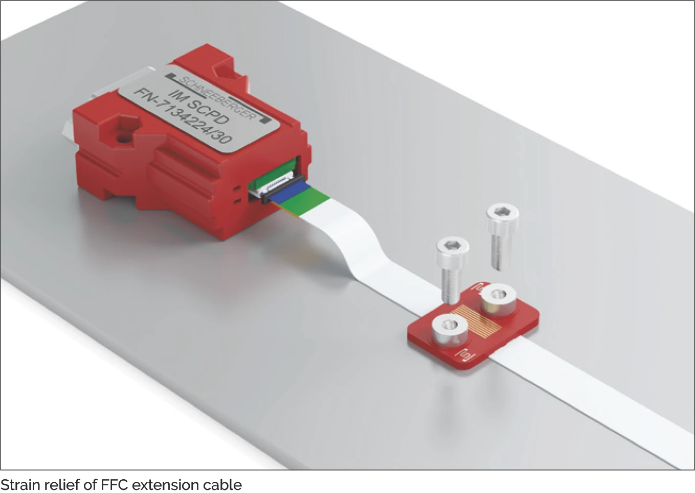
Strain relief mounting options for the FFC extension cable
4.7 Connecting a Customer-provided Cable
If the interface module is not mounted directly on a PCB, it must be connected to the controller by a customer-provided cable.
4.7.1 Recommendations for the customer-provided cable
- In order to ensure maximum resistance to interference, a shielded twisted pair cable is recommended. A cable with additional shielding should be used if necessary.
- Suitable shielding must be ensured in any case.
- The cable shielding must not act as a potential equalization conductor.
- Place the encoder cable apart from the power cables and ensure that the two are not parallel.
- If the cable is to be run through a cable carrier, a flexible cable that is suitable for this purpose should be used.
- Keep the cable short (The cable length between the interface module and the controller should not exceed 30 meters).
- The maximum cable length is reduced when increasing speeds in connection with the digital interface module.
- Example: For a maximum speed of 3.2 m/s (digital), the data rate is 8 MHz. This corresponds to a maximum cable length of 15 meters.
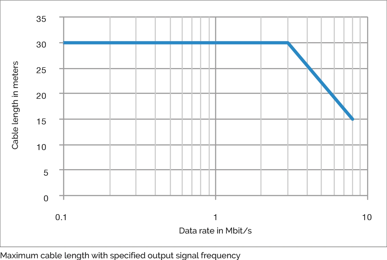
Maximum cable length at specified output signal frequency
4.7.2 Example cable and connectors for interface module
| Cable: | Igus Chainflex, Igus number CF11.02.05.02 |
| Micro-Match socket 10P | |
| Straight: | TE Connectivity, TE number 8-215079-0 |
| 90° angle: | TE Connectivity, TE number 8-215460-0 |
| D-Sub 9 socket 9P | |
| Solder terminal type: | TE Connectivity, TE number 3-1393483-8 |