This chapter details the various installation methods, rail options, fixing hole closures, length tolerances, screw torque specifications, and factors affecting installation accuracy for SCHNEEBERGER MONORAIL guide rails.
4.9.1 Methods of Attachment
MONORAIL guide rails can be fastened in two ways. Standard rails (N) and rails for cover strips (C) have continuous fixing holes with countersunk holes for fastening from above. Additionally, rails with threaded fixing holes at the bottom (U) are available, which can be bolted from below the machine table. The following overview shows the advantages and disadvantages of both fastening methods.
Fastening from Above (N, ND, C, CD)
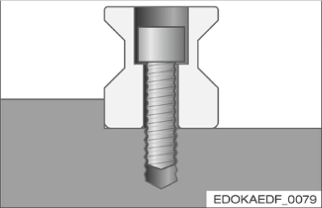
Advantages
- Easy accessibility
Disadvantages
- Rail fixing holes must be closed with plugs or cover strips to protect wipers
- Protruding edges due to closures: wiper wear, contamination
Fastening from Below (NU, NUD)
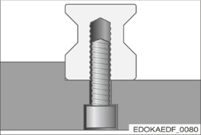
Advantages
- No closures required for rail fixing holes
- No protruding edges on rail surface
Disadvantages
- Limited accessibility
- Lower clamping force due to longer screws
4.9.2 Rail Options
Special Fixing Hole Spacing L4
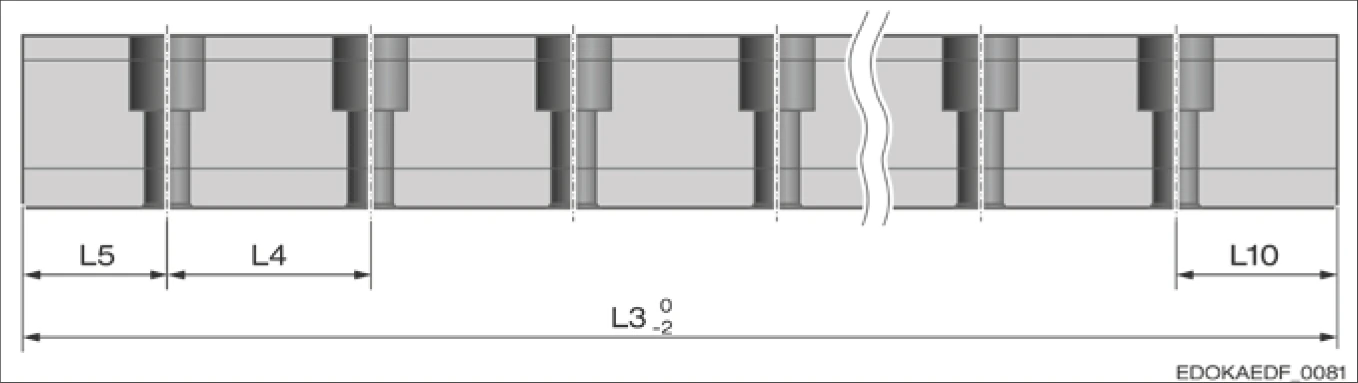
Fixing hole spacing diagram
Fixing Hole Spacing Description:
- L5 - Starting fixing hole spacing
- L4 - Fixing hole spacing
- L3 - Rail length
- L10 - End fixing hole spacing
Double or Half Fixing Hole Spacing L4
On request, MONORAIL MR rails can be supplied with double fixing hole spacing L4. This is not a standard product (order code NX). Availability needs to be confirmed. It should be noted that rigidity and running accuracy will be reduced in this case.
For MONORAIL BM rails, rails with half fixing hole spacing (corresponding to MR standard L4) are also available to increase rigidity and improve running accuracy. This is not a standard product (order code NX). Availability needs to be confirmed.
Other Special Fixing Hole Spacings
Customer-specific fixing hole spacings or varying fixing hole spacings along the rail length, for example at joints of multi-segment rails, can be provided on request.
Additional Locating Fixing Holes and Threads
Rails with additional fixing holes, for example for locating pins, or rails with additional threaded holes are optionally available. Availability needs to be confirmed.
Additional Fixing Holes on Rail Top Surface
Additional fixing holes can be machined on the rail top surface according to customer-specific specifications, for example for locating pins or through holes (e.g., for mounting carriages). Availability needs to be confirmed.
Rail End Machining
Rail ends are machined after separating the rails.
Standard Design:
- Chamfer for transferring carriages
- Prevention of damage
- For rails with cover strips, provides clean support for cover strips
Standard
Important: Special rail options need to be planned in advance and confirmed with the SCHNEEBERGER technical team for feasibility and delivery time. These options may affect rail performance characteristics, and detailed discussion during the design phase is recommended.
4.9.3 Closures for Fixing Holes
The following closures are available for rail fixing holes:
A comparison of the advantages and disadvantages of various element types can be found in Section 4.3 - Rail Types.
For available sizes, types, and ordering details, please refer to the SCHNEEBERGER MONORAIL and AMS product catalog; for installation information, please refer to the SCHNEEBERGER steel plug and brass plug installation instructions.
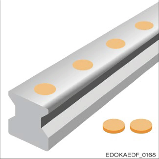
Plastic Plugs
Features:
- Inexpensive
- Easy to install and remove
- Suitable for protected axes and clean working environments, e.g., handling applications
- Roller product order code: MRK
- Ball product order code: BRK
- Cannot be reused
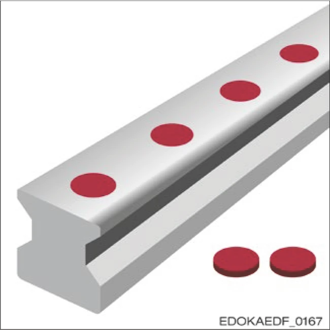
Brass Plugs
Features:
- Inexpensive
- Smooth and gap-free surface
- Excellent scraping function
- Suitable for higher thermal loads and mechanical stresses
- Liquid-tight
- Requires hydraulic installation tool for assembly
- Cannot be reused
- Roller product order code: MRS
- Ball product order code: BRS
Steel Plugs
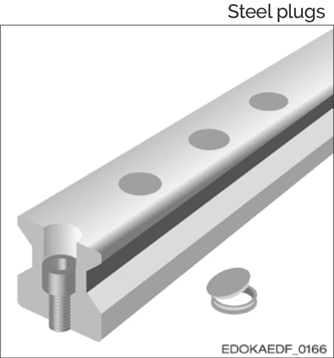
Features:
- Smooth rail surface
- Good scraping function
- Suitable for high mechanical and thermal stresses, e.g., outdoor environments, chip zones
- Simple assembly using hydraulic installation tool
- Expensive
- Cannot be reused
- Roller product order code: MRZ
Cover Strips
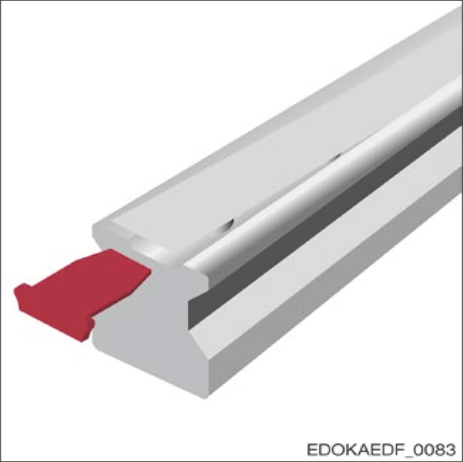
Features:
- Smooth rail surface with only one protruding edge in the longitudinal direction
- Good scraping function
- Minimal installation effort using installation tool
- Only one closure required for entire rail
- Can be reused multiple times and easily removed
- Free space required behind rail during installation
- Cover strip ends secured with end pieces (EST) or fixing bands (BSC)
- Roller product order code: MAC
- Ball product order code: BAC
4.9.4 Rail Length Tolerances
Rail Length Tolerances and Rail Fixing Hole Tolerances for N, ND, NU, NUD, C and CD Type Rails
Longitudinal tolerances for single and multi-segment rails are: L3 = -/-2 mm
Position tolerances for fixing holes of single and multi-segment rails are as follows:
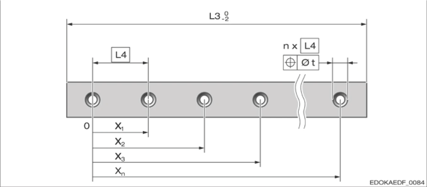
Fixing hole spacing diagram L4:
L4 = Fixing hole spacing
L3 = Rail length
| Position Tolerance t (mm) | ||
|---|---|---|
| Rail | xn ≤ 1000 mm | xn > 1000 mm |
| Induction Hardened | 0.4 | 0.4 |
| Fully Hardened | 0.6 | 0.8 |
4.9.5 Permissible Screw Tightening Torques
The following table lists the maximum tightening torques for DIN 912 / ISO 4762 fixing screws. These values are based on the friction coefficient μ = 0.125 in the as-delivered condition.

Caution
Component damage from incorrect screw tightening torque
- Screw supplier recommendations must be followed and are always binding.
- Low head screws DIN 6912 should be tightened according to strength class 8.8.
- AMS rails should use 8.8 grade screws.
Tightening Torques for Fixing Screws ISO 4762:
| Maximum Tightening Torque (Nm) | ||||||||
|---|---|---|---|---|---|---|---|---|
| Screw | M4 | M5 | M6 | M8 | M12 | M14 | M16 | M24 |
| Size | (15) | (20) | (25) | (30, 35) | (45) | (55) | (65) | (100) |
| Strength Class 8.8 | 3 | 6 | 10 | 24 | 83 | 130 | 200 | 700 |
| Strength Class 12.9 | 5 | 10 | 16 | 40 | 95 | 166 | 265 | 1100 |
Note: Values in parentheses in the table indicate screw lengths (mm).
4.9.6 Permissible Lateral Force Without Locating Surface
For cases where no locating surface is provided, guidance values for maximum permissible lateral forces can be obtained from the following table.
FSide_max values depend on dynamic load capacity C, carriage fastening type, and screw strength class.
Note: Based on strength class 8.8 screw connections. Values in the table represent maximum lateral forces applied by one carriage to the rail, applicable for standard fixing hole spacing L4. When using two or more carriages, values increase accordingly.

MONORAIL MR Maximum Lateral Force FLateral_max (N)
| Size | Carriage Types A, C, E | Carriage Types B, D |
|---|---|---|
| 25 | 1400 | 1600 |
| 30 | 2800 | 3200 |
| 35 | 2800 | 3200 |
| 45 | 6900 | 7900 |
| 55 | 9600 | 10900 |
| 65 | 13200 | 15100 |
| 100 | 31500 | 36000 |
MONORAIL BM Maximum Lateral Force FLateral_max (N)
| Size | Carriage Types A, C, E, F | Carriage Types B, D, G |
|---|---|---|
| 15 | 280 | 320 |
| 20 | 480 | 550 |
| 25 | 710 | 810 |
| 30 | 1400 | 1600 |
| 35 | 1400 | 1600 |
| 45 | 3400 | 3900 |
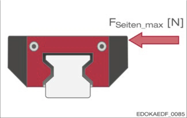
Maximum Lateral Force FSide_max (N) Acting on Single Carriage
The listed maximum lateral forces apply only to ideally rigid connection surfaces in the connecting structure and steel or cast steel screw fasteners. In cases of unstable connection surfaces, screw loads increase significantly and may cause screw connection loosening. For aluminum screw fasteners, maximum permissible lateral forces should be reduced according to VDI 2230 standard.
4.9.7 Permissible Tensile Forces and Lateral Torques
The maximum load of profiled rail systems is determined not only by the static load capacity C0 and static moment M0 of the rolling contact, but also by the screw connections of carriages and rails. In this case, the screw connection of the rail determines the maximum load limit.
Maximum Tensile Force FTension_max and Lateral Torque MQ_max for Profiled Rail Systems
Note: Based on strength class 8.8 screw connections. Values in the table represent maximum permissible tensile forces and lateral torques applied by one carriage to the rail, applicable for standard fixing hole spacing L4.
MONORAIL MR Maximum Tensile Forces and Lateral Torques
| Size | Carriage Types A, C, E | Carriage Types B, D | ||
|---|---|---|---|---|
| FTension_max (N) | MQ_max (Nm) | FTension_max (N) | MQ_max (Nm) | |
| 25 | 18800 | 200 | 21500 | 230 |
| 30 | 37000 | 490 | 42300 | 560 |
| 35 | 36900 | 590 | 42200 | 680 |
| 45 | 91700 | 1900 | 104800 | 2200 |
| 55 | 127400 | 3200 | 145600 | 3600 |
| 65 | 176400 | 5200 | 201700 | 6000 |
| 100 | 419400 | 19700 | 479300 | 22500 |
MONORAIL BM Maximum Tensile Forces and Lateral Torques
| Size | Carriage Types A, C, E, F | Carriage Types B, D, G | ||
|---|---|---|---|---|
| FTension_max (N) | MQ_max (Nm) | FTension_max (N) | MQ_max (Nm) | |
| 15 | 3700 | 26 | 4200 | 30 |
| 20 | 6400 | 60 | 7300 | 68 |
| 25 | 9400 | 100 | 10800 | 120 |
| 30 | 18500 | 240 | 21100 | 280 |
| 35 | 18500 | 300 | 21100 | 340 |
| 45 | 45900 | 970 | 52400 | 1100 |
Note: For detailed values and data for other series (such as AMS), please refer to the SCHNEEBERGER MONORAIL and AMS product catalog.
Precautions
When exceeding these values, always check screw connections. For this purpose, you may need to loosen the screw connections.
The listed maximum tensile forces and torques apply only to ideally rigid connection surfaces in the connecting structure and steel or cast steel screw fasteners. In cases of unstable connection surfaces, screw loads increase significantly and may cause screw connection loosening. For aluminum screw fasteners, maximum tensile forces and lateral torques should be reduced according to VDI 2230 standard.
4.9.8 Factors Affecting Accuracy
The accuracy of rail fastening is affected by a series of factors:
| Influencing Factor | Description |
|---|---|
| Accuracy of connecting structure | Surface accuracy is directly transferred to the rail: insufficient quality shortens service life |
| Straightness of rail | No kinks, compliant with SCHNEEBERGER specifications |
| Fixing hole spacing | Screws cannot be installed in the machine bed but remain in the rail fixing holes |
| Installation method (with/without lateral locating surface) | When applicable, limits straightness |
| Tightening torque | Ensure uniform screw tightening |
| Use of flat washers | Ensure flat washers are not positioned over fixing holes and do not limit plug installation space |
| Lubrication condition of machine bed, rails, and screws | Clean all components |
| Installation method (tighten screws at once or pre-align with lower torque first) | See MONORAIL and AMS installation instructions |
| Tightening sequence for fixing holes | See MONORAIL and AMS installation instructions |
| Temperature difference between rail and machine bed during installation (thermal expansion) | Ensure rail and machine bed are at the same temperature during installation |
Detailed Information
For detailed information on each point, please refer to:
- SCHNEEBERGER MONORAIL and AMS product catalog and installation instructions
- Section 1.6 - Accuracy
- Section 1.7 - Straightness and Rail Curvature
- Section 4.7 - Straightness