Drawing
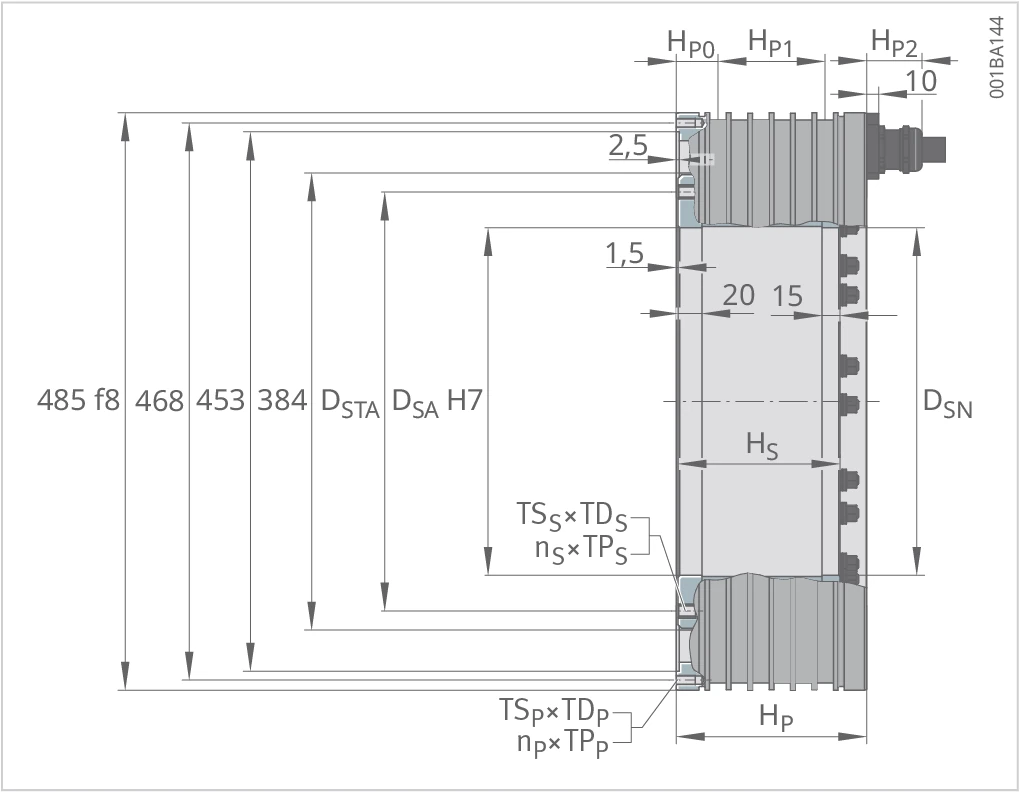
RKIB5-3P-384xH drawing — outer diameter 485 f8, centring diameters 468/453/384, and DSTA/DSA (H7); primary part height HP, secondary part height HS, including the housing and cooling inlet/outlet distances (HP0/HP1), the axial and right-angle cable screw heights (HP2/HP3, including 10), air-gap annotations 2,5 and 1,5, 20/15, secondary part inner diameter DSN, and the primary/secondary part threads (TSP×TDP, nP×TPP, TSS×TDS, nS×TPS). Magnet configurations R20/R22 and V22, axial cable outlet 2×4G10 (cable outlet spacing 135/55,5).
Description
RKI and RKIB are internal running permanent-magnet synchronous torque motors with a built-in secondary part. The primary part is a fully encapsulated, water-cooled laminated iron core. The secondary part's permanent magnets are integrated into the lamination stack, which provides the magnetic return path. The magnet configuration variants R20, V22 and R22 correspond to different cost-effectiveness ratios and attraction characteristics. The RKIB5-3P-384xH is divided by active height from 384×50 to 384×175, and split by size subset into Part 1 (384×50 to 384×125) and Part 2 (384×150 to 384×175).
Part 1 (sizes 384×50 to 384×125)
Geometric Data — Part 1
Notes
Tolerance range ±10%. Each column is a "size × magnet configuration" combination. In the type designation D×H represents "effective air-gap diameter × active height" (in mm).
| Geometric data | Symbol | Unit | 384×50 | 384×50 | 384×50 | 384×75 | 384×75 | 384×75 | 384×100 | 384×100 | 384×100 | 384×125 | 384×125 | 384×125 |
|---|---|---|---|---|---|---|---|---|---|---|---|---|---|---|
| Magnet configuration & Winding design | ||||||||||||||
| Magnet configuration | — | — | R20 | V22 | R22 | R20 | V22 | R22 | R20 | V22 | R22 | R20 | V22 | R22 |
| Winding design | — | — | Z5.8 | Z5.8 | Z5.8 | Z5.8 | Z5.8 | Z5.8 | Z5.8 | Z5.8 | Z5.8 | Z7.2 | Z7.2 | Z7.2 |
| Power cable | — | — | 2×4G10 | 2×4G10 | 2×4G10 | 2×4G10 | 2×4G10 | 2×4G10 | 2×4G10 | 2×4G10 | 2×4G10 | 2×4G16 | 2×4G16 | 2×4G16 |
| Mass & Height | ||||||||||||||
| Mass, secondary part | mS | kg | 21.8 | 16.3 | 22.8 | 30.0 | 21.8 | 31.4 | 38.1 | 27.5 | 40.0 | 46.3 | 33.2 | 48.7 |
| Mass, primary part | mP | kg | 41.0 | 41.0 | 41.0 | 52.0 | 52.0 | 52.0 | 65.7 | 65.7 | 65.7 | 78.6 | 78.6 | 78.6 |
| Height, secondary part | HS | mm | 86 | 86 | 86 | 111 | 111 | 111 | 136 | 136 | 136 | 161 | 161 | 161 |
| Height, primary part | HP | mm | 110 | 110 | 110 | 130 | 130 | 130 | 160 | 160 | 160 | 185 | 185 | 185 |
| Distance between housing and cooling inlet | HP0 | mm | 33 | 33 | 33 | 33 | 33 | 33 | 35 | 35 | 35 | 35 | 35 | 35 |
| Distance between cooling inlet and cooling outlet | HP1 | mm | 45 | 45 | 45 | 65 | 65 | 65 | 90 | 90 | 90 | 116 | 116 | 116 |
| Height, axial cable screw | HP2 | mm | 46.5 | 46.5 | 46.5 | 46.5 | 46.5 | 46.5 | 46.5 | 46.5 | 46.5 | 46.5 | 46.5 | 46.5 |
| Height, right-angle cable screw | HP3 | mm | 53.8 | 53.8 | 53.8 | 53.8 | 53.8 | 53.8 | 53.8 | 53.8 | 53.8 | 53.8 | 53.8 | 53.8 |
| Diameters & Threads | ||||||||||||||
| Thread pitch diameter, secondary part, assembly side | DSTA | mm | 352 | 360 | 352 | 352 | 360 | 352 | 352 | 360 | 352 | 352 | 360 | 352 |
| Inner diameter, secondary part, assembly side | DSA | mm | 292 | 310 | 292 | 292 | 310 | 292 | 292 | 310 | 292 | 292 | 310 | 292 |
| Inner diameter, secondary part, non-assembly side | DSN | mm | 292 | 312 | 292 | 292 | 312 | 292 | 292 | 312 | 292 | 292 | 312 | 292 |
| Thread, secondary part | TSS×TDS | – | M10×15 | M10×15 | M10×15 | M10×15 | M10×15 | M10×15 | M10×15 | M10×15 | M10×15 | M10×15 | M10×15 | M10×15 |
| Thread, secondary part, number×pitch | nS×TPS | ° | 24×15 | 30×12 | 24×15 | 24×15 | 30×12 | 24×15 | 24×15 | 30×12 | 24×15 | 24×15 | 30×12 | 24×15 |
| Thread, primary part, cable side | TSPC×TDPC | – | M8×16 | M8×16 | M8×16 | M8×16 | M8×16 | M8×16 | M8×16 | M8×16 | M8×16 | M8×16 | M8×16 | M8×16 |
| Thread, primary part, cable side, number×pitch | nPC×TPPC | ° | 11×30 | 11×30 | 11×30 | 11×30 | 11×30 | 11×30 | 21×15 | 21×15 | 21×15 | 21×15 | 21×15 | 21×15 |
| Thread, primary part | TSP×TDP | – | M8×16 | M8×16 | M8×16 | M8×16 | M8×16 | M8×16 | M8×16 | M8×16 | M8×16 | M8×16 | M8×16 | M8×16 |
| Thread, primary part, number×pitch | nP×TPP | ° | 12×30 | 12×30 | 12×30 | 12×30 | 12×30 | 12×30 | 24×15 | 24×15 | 24×15 | 24×15 | 24×15 | 24×15 |
Performance Data — Part 1
Notes
Tolerance range ±10%. Each column is a "size × magnet configuration × winding design" combination. Nominal feed temperature of the cooling water +20 °C.
| Performance data | Symbol | Unit | 384×50 R20 · Z5.8 | 384×50 V22 · Z5.8 | 384×50 R22 · Z5.8 | 384×75 R20 · Z5.8 | 384×75 V22 · Z5.8 | 384×75 R22 · Z5.8 | 384×100 R20 · Z5.8 | 384×100 V22 · Z5.8 | 384×100 R22 · Z5.8 | 384×125 R20 · Z7.2 | 384×125 V22 · Z7.2 | 384×125 R22 · Z7.2 |
|---|---|---|---|---|---|---|---|---|---|---|---|---|---|---|
| Torques | ||||||||||||||
| Ultimate torque | Tu | Nm | 1164 | 1230 | 1440 | 1746 | 1846 | 2161 | 2327 | 2461 | 2881 | 2909 | 3076 | 3601 |
| Peak torque | Tp | Nm | 1040 | 1146 | 1275 | 1559 | 1719 | 1912 | 2079 | 2291 | 2549 | 2599 | 2864 | 3186 |
| Continuous torque, cooled | Tcw | Nm | 646 | 728 | 761 | 994 | 1120 | 1172 | 1314 | 1480 | 1549 | 1643 | 1851 | 1937 |
| Torque at Icw2 eff and nlw2 | Tcw2 | Nm | 595 | 669 | 701 | 916 | 1030 | 1079 | 1210 | 1361 | 1425 | 1514 | 1702 | 1782 |
| Torque at Icw2 eff and nlw3 | Tcw3 | Nm | 399 | 434 | 597 | 417 | 443 | 537 | 399 | 425 | 394 | 722 | 764 | 1035 |
| Continuous torque, not cooled | Tc | Nm | 251 | 263 | 285 | 376 | 395 | 428 | 502 | 527 | 571 | 627 | 652 | 706 |
| Stall torque, cooled at Isw eff | Tsw | Nm | 498 | 553 | 585 | 767 | 851 | 901 | 1013 | 1124 | 1191 | 1267 | 1406 | 1489 |
| Cogging torque | Tcog | Nm | 2.0 | 2.1 | 2.4 | 3.1 | 3.2 | 3.6 | 4.1 | 4.3 | 4.8 | 5.4 | 5.6 | 6.3 |
| Speeds | ||||||||||||||
| Limiting speed at Ip eff and UDCL | nlp | min⁻¹ | 476 | 466 | 485 | 321 | 314 | 329 | 241 | 236 | 246 | 285 | 279 | 293 |
| Knee speed | nlw | min⁻¹ | 611 | 589 | 594 | 407 | 392 | 397 | 308 | 296 | 298 | 361 | 347 | 351 |
| Rated speed S1, cooled | nlwS1 | min⁻¹ | 200 | 200 | 200 | 200 | 200 | 200 | 200 | 200 | 200 | 200 | 200 | 200 |
| Operating speed FS at Icw2 eff and UDCL | nlw2 | min⁻¹ | 630 | 607 | 606 | 419 | 404 | 405 | 316 | 304 | 304 | 371 | 357 | 357 |
| Limiting speed at Icw2 eff and UDCL in continuous operation | nlw3 | min⁻¹ | 1100 | 1100 | 800 | 1100 | 1100 | 800 | 1100 | 1100 | 800 | 900 | 900 | 600 |
| Currents | ||||||||||||||
| Effective ultimate current | Iu eff | A | 216.8 | 216.8 | 216.8 | 216.8 | 216.8 | 216.8 | 216.8 | 216.8 | 216.8 | 314.8 | 314.8 | 314.8 |
| Effective peak current | Ip eff | A | 173.4 | 173.4 | 173.4 | 173.4 | 173.4 | 173.4 | 173.4 | 173.4 | 173.4 | 251.8 | 251.8 | 251.8 |
| Effective continuous current, cooled | Icw eff | A | 85.9 | 85.9 | 85.9 | 88.2 | 88.2 | 88.2 | 87.4 | 87.4 | 87.4 | 127.0 | 127.0 | 127.0 |
| Effective continuous current for higher speeds (S1) | Icw2 eff | A | 77.3 | 77.3 | 77.3 | 79.4 | 79.4 | 79.4 | 78.7 | 78.7 | 78.7 | 114.3 | 114.3 | 114.3 |
| Effective continuous current, not cooled | Ic eff | A | 28.3 | 28.3 | 28.3 | 28.3 | 28.3 | 28.3 | 28.3 | 28.3 | 28.3 | 40.7 | 40.7 | 40.7 |
| Effective stall current, cooled | Isw eff | A | 61.9 | 61.9 | 61.9 | 63.5 | 63.5 | 63.5 | 62.9 | 62.9 | 62.9 | 91.4 | 91.4 | 91.4 |
| Power losses | ||||||||||||||
| Power loss at Tp | Plp | W | 8292 | 8292 | 8292 | 10805 | 10805 | 10805 | 13318 | 13318 | 13318 | 16330 | 16330 | 16330 |
| Power loss at Tcw | Plw | W | 2732 | 2732 | 2732 | 3749 | 3749 | 3749 | 4539 | 4539 | 4539 | 5570 | 5570 | 5570 |
| Power loss at Tc | Plc | W | 221 | 221 | 221 | 288 | 288 | 288 | 356 | 356 | 356 | 427 | 427 | 427 |
| Mechanical power | ||||||||||||||
| Max. rated power | Pmax S1 | W | 46000 | 50000 | 50000 | 48000 | 51000 | 45000 | 46000 | 49000 | 33000 | 68000 | 72000 | 65000 |
| Electrical characteristic values | ||||||||||||||
| DC link voltage | UDCL | V | 600 | 600 | 600 | 600 | 600 | 600 | 600 | 600 | 600 | 600 | 600 | 600 |
| Electrical resistance, phase to phase | R20 | Ω | 0.18 | 0.18 | 0.18 | 0.24 | 0.24 | 0.24 | 0.30 | 0.30 | 0.30 | 0.17 | 0.17 | 0.17 |
| Inductance, phase to phase | L | mH | 2.1 | 2.0 | 1.6 | 3.0 | 2.8 | 2.3 | 3.9 | 3.7 | 2.9 | 2.3 | 2.2 | 1.7 |
| Back EMF constant, phase to phase | kû | V/(rad/s) | 7.3 | 7.6 | 8.2 | 11.0 | 11.4 | 12.3 | 14.6 | 15.2 | 16.4 | 12.6 | 13.1 | 14.2 |
| General characteristic values | ||||||||||||||
| Number of pole pairs | P | – | 30 | 30 | 30 | 30 | 30 | 30 | 30 | 30 | 30 | 30 | 30 | 30 |
| Motor constant at +20 °C | km | Nm/√W | 17.0 | 17.7 | 19.2 | 22.4 | 23.3 | 25.2 | 26.9 | 28.0 | 30.3 | 30.4 | 31.6 | 34.2 |
| Torque constant | kT | Nm/A | 8.9 | 9.3 | 10.1 | 13.4 | 14.0 | 15.1 | 17.9 | 18.6 | 20.1 | 15.4 | 16.0 | 17.3 |
| Motor temperature switch-off threshold | ϑPTC | °C | 110 | 110 | 110 | 110 | 110 | 110 | 110 | 110 | 110 | 110 | 110 | 110 |
| Axial attraction | Fa | kN | 0.61 | 0.65 | 1.00 | 0.61 | 0.65 | 1.00 | 0.61 | 0.65 | 1.00 | 0.61 | 0.65 | 1.00 |
| Radial attraction | Fr | kN/mm | 9.0 | 9.3 | 10.4 | 13.5 | 13.9 | 15.6 | 18.0 | 18.5 | 20.8 | 22.5 | 23.2 | 26.0 |
| Moment of inertia, secondary part | J | kg·m² | 0.628 | 0.500 | 0.655 | 0.865 | 0.673 | 0.905 | 1.102 | 0.850 | 1.155 | 1.338 | 1.027 | 1.405 |
| Cooling conditions | ||||||||||||||
| Volume flow | dV/dt | l/min | 7.8 | 7.8 | 7.8 | 10.7 | 10.7 | 10.7 | 13.0 | 13.0 | 13.0 | 16.0 | 16.0 | 16.0 |
| Nominal feed temperature | ϑnf | °C | 20 | 20 | 20 | 20 | 20 | 20 | 20 | 20 | 20 | 20 | 20 | 20 |
| Cooling water temperature difference | ∆ϑ | K | 5.0 | 5.0 | 5.0 | 5.0 | 5.0 | 5.0 | 5.0 | 5.0 | 5.0 | 5.0 | 5.0 | 5.0 |
Part 2 (sizes 384×150 to 384×175)
Geometric Data — Part 2
Notes
Tolerance range ±10%. Each column is a "size × magnet configuration" combination. In the type designation D×H represents "effective air-gap diameter × active height" (in mm).
| Geometric data | Symbol | Unit | 384×150 | 384×150 | 384×150 | 384×175 | 384×175 | 384×175 |
|---|---|---|---|---|---|---|---|---|
| Magnet configuration & Winding design | ||||||||
| Magnet configuration | — | — | R20 | V22 | R22 | R20 | V22 | R22 |
| Winding design | — | — | Z8.4 | Z8.4 | Z8.4 | Z8.4 | Z8.4 | Z8.4 |
| Power cable | — | — | 4×4G10 | 4×4G10 | 4×4G10 | 4×4G10 | 4×4G10 | 4×4G10 |
| Mass & Height | ||||||||
| Mass, secondary part | mS | kg | 54.5 | 38.9 | 57.3 | 62.6 | 44.5 | 65.9 |
| Mass, primary part | mP | kg | 91.4 | 91.4 | 91.4 | 104.1 | 104.1 | 104.1 |
| Height, secondary part | HS | mm | 186 | 186 | 186 | 211 | 211 | 211 |
| Height, primary part | HP | mm | 210 | 210 | 210 | 235 | 235 | 235 |
| Distance between housing and cooling inlet | HP0 | mm | 35 | 35 | 35 | 37 | 37 | 37 |
| Distance between cooling inlet and cooling outlet | HP1 | mm | 140 | 140 | 140 | 161 | 161 | 161 |
| Height, axial cable screw | HP2 | mm | 46.5 | 46.5 | 46.5 | 46.5 | 46.5 | 46.5 |
| Height, right-angle cable screw | HP3 | mm | 53.8 | 53.8 | 53.8 | 53.8 | 53.8 | 53.8 |
| Diameters & Threads | ||||||||
| Thread pitch diameter, secondary part, assembly side | DSTA | mm | 352 | 360 | 352 | 352 | 360 | 352 |
| Inner diameter, secondary part, assembly side | DSA | mm | 292 | 310 | 292 | 292 | 310 | 292 |
| Inner diameter, secondary part, non-assembly side | DSN | mm | 292 | 312 | 292 | 292 | 312 | 292 |
| Thread, secondary part | TSS×TDS | – | M10×15 | M10×15 | M10×15 | M10×15 | M10×15 | M10×15 |
| Thread, secondary part, number×pitch | nS×TPS | ° | 24×15 | 30×12 | 24×15 | 24×15 | 30×12 | 24×15 |
| Thread, primary part, cable side | TSPC×TDPC | – | M8×16 | M8×16 | M8×16 | M8×16 | M8×16 | M8×16 |
| Thread, primary part, cable side, number×pitch | nPC×TPPC | ° | 18×15 | 18×15 | 18×15 | 38×7.5 | 38×7.5 | 38×7.5 |
| Thread, primary part | TSP×TDP | – | M8×16 | M8×16 | M8×16 | M8×16 | M8×16 | M8×16 |
| Thread, primary part, number×pitch | nP×TPP | ° | 24×15 | 24×15 | 24×15 | 48×7.5 | 48×7.5 | 48×7.5 |
Performance Data — Part 2
Notes
Tolerance range ±10%. Each column is a "size × magnet configuration × winding design" combination. Nominal feed temperature of the cooling water +20 °C.
| Performance data | Symbol | Unit | 384×150 R20 · Z8.4 | 384×150 V22 · Z8.4 | 384×150 R22 · Z8.4 | 384×175 R20 · Z8.4 | 384×175 V22 · Z8.4 | 384×175 R22 · Z8.4 |
|---|---|---|---|---|---|---|---|---|
| Torques | ||||||||
| Ultimate torque | Tu | Nm | 3491 | 3691 | 4321 | 4073 | 4306 | 5041 |
| Peak torque | Tp | Nm | 3119 | 3437 | 3824 | 3638 | 4010 | 4461 |
| Continuous torque, cooled | Tcw | Nm | 2025 | 2281 | 2387 | 2382 | 2684 | 2808 |
| Torque at Icw2 eff and nlw2 | Tcw2 | Nm | 1866 | 2098 | 2197 | 2195 | 2469 | 2585 |
| Torque at Icw2 eff and nlw3 | Tcw3 | Nm | 1040 | 1103 | 1592 | 1008 | 1072 | 1480 |
| Continuous torque, not cooled | Tc | Nm | 761 | 792 | 857 | 880 | 915 | 990 |
| Stall torque, cooled at Isw eff | Tsw | Nm | 1267 | 1406 | 1489 | 1267 | 1406 | 1489 |
| Cogging torque | Tcog | Nm | 6.4 | 6.7 | 7.5 | 7.5 | 7.9 | 8.8 |
| Speeds | ||||||||
| Limiting speed at Ip eff and UDCL | nlp | min⁻¹ | 335 | 328 | 344 | 285 | 279 | 293 |
| Knee speed | nlw | min⁻¹ | 416 | 400 | 404 | 354 | 341 | 345 |
| Rated speed S1, cooled | nlwS1 | min⁻¹ | 200 | 200 | 200 | 200 | 200 | 200 |
| Operating speed FS at Icw2 eff and UDCL | nlw2 | min⁻¹ | 427 | 411 | 411 | 364 | 350 | 351 |
| Limiting speed at Icw2 eff and UDCL in continuous operation | nlw3 | min⁻¹ | 900 | 900 | 600 | 900 | 900 | 600 |
| Currents | ||||||||
| Effective ultimate current | Iu eff | A | 433.6 | 433.6 | 433.6 | 433.6 | 433.6 | 433.6 |
| Effective peak current | Ip eff | A | 346.8 | 346.8 | 346.8 | 346.8 | 346.8 | 346.8 |
| Effective continuous current, cooled | Icw eff | A | 179.6 | 179.6 | 179.6 | 181.1 | 181.1 | 181.1 |
| Effective continuous current for higher speeds (S1) | Icw2 eff | A | 161.7 | 161.7 | 161.7 | 163.0 | 163.0 | 163.0 |
| Effective continuous current, not cooled | Ic eff | A | 56.7 | 56.7 | 56.7 | 56.2 | 56.2 | 56.2 |
| Effective stall current, cooled | Isw eff | A | 129.3 | 129.3 | 129.3 | 130.4 | 130.4 | 130.4 |
| Power losses | ||||||||
| Power loss at Tp | Plp | W | 18343 | 18343 | 18343 | 20856 | 20856 | 20856 |
| Power loss at Tcw | Plw | W | 6602 | 6602 | 6602 | 7633 | 7633 | 7633 |
| Power loss at Tc | Plc | W | 491 | 491 | 491 | 548 | 548 | 548 |
| Mechanical power | ||||||||
| Max. rated power | Pmax S1 | W | 98000 | 104000 | 100000 | 95000 | 101000 | 93000 |
| Electrical characteristic values | ||||||||
| DC link voltage | UDCL | V | 600 | 600 | 600 | 600 | 600 | 600 |
| Electrical resistance, phase to phase | R20 | Ω | 0.10 | 0.10 | 0.10 | 0.12 | 0.12 | 0.12 |
| Inductance, phase to phase | L | mH | 1.4 | 1.3 | 1.0 | 1.6 | 1.6 | 1.2 |
| Back EMF constant, phase to phase | kû | V/(rad/s) | 11.0 | 11.4 | 12.3 | 12.8 | 13.3 | 14.4 |
| General characteristic values | ||||||||
| Number of pole pairs | P | – | 30 | 30 | 30 | 30 | 30 | 30 |
| Motor constant at +20 °C | km | Nm/√W | 34.4 | 35.7 | 38.7 | 37.6 | 39.1 | 42.3 |
| Torque constant | kT | Nm/A | 13.4 | 14.0 | 15.1 | 15.7 | 16.3 | 17.6 |
| Motor temperature switch-off threshold | ϑPTC | °C | 110 | 110 | 110 | 110 | 110 | 110 |
| Axial attraction | Fa | kN | 0.61 | 0.65 | 1.00 | 0.61 | 0.65 | 1.00 |
| Radial attraction | Fr | kN/mm | 27.0 | 27.8 | 31.2 | 31.5 | 32.4 | 36.4 |
| Moment of inertia, secondary part | J | kg·m² | 1.575 | 1.204 | 1.655 | 1.812 | 1.381 | 1.905 |
| Cooling conditions | ||||||||
| Volume flow | dV/dt | l/min | 18.9 | 18.9 | 18.9 | 21.9 | 21.9 | 21.9 |
| Nominal feed temperature | ϑnf | °C | 20 | 20 | 20 | 20 | 20 | 20 |
| Cooling water temperature difference | ∆ϑ | K | 5.0 | 5.0 | 5.0 | 5.0 | 5.0 | 5.0 |
Note: Tolerance range of all values ±10%. Binding data and drawings will be made available by agreement; we recommend obtaining support from our engineers in the motor design phase. Subject to change without notice.