以下计算范例说明了一些典型问题的处理程序。
范例 1:每个滚子的当量载荷 P
Example 1: Equivalent load P per roller
假设条件 (Assumption):
- 直线导轨型号 R 6 (Linear guides type R 6)
- AC 6 保持架,8 个滚子 (AC 6 cage with 8 rollers, RA = 8)
- 负载 F = 350 N
- 杠杆臂距离 X = 120 mm
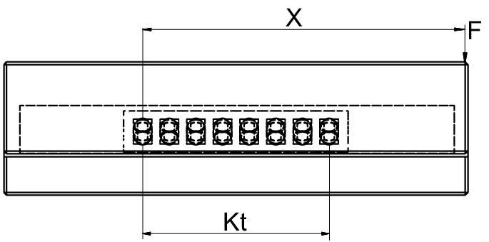
图 1:单导轨配置的力学模型,显示负载 F、杠杆臂距离 X 和负载长度 Kt
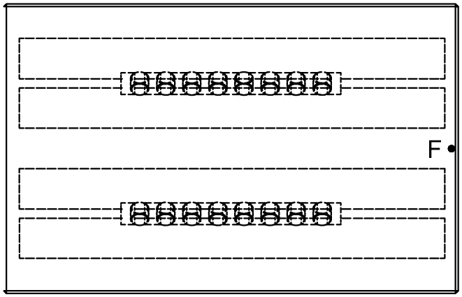
图 2:双导轨配置的俯视图,显示力的分布
对于 AC 6 型滚子保持架,适用以下条件:
For the roller cage type AC 6 the following applies:
P 每个滚子的计算 (Calculation for P per roller)
P 小于 C,因此此设计是正确的。
P is smaller than C. The design is correct in this way.
注意:
力的非对称分布最安全的考虑方式是减少导轨的负载滚动元件数量 (Rtmin)。
The asymmetric distribution of force is most safely taken into account when the load on the number of load bearing rolling elements (Rtmin) for the guideway is reduced.
符号说明 (Symbol Definitions)
| P | 每个滚子的当量载荷 (N) | Equivalent load in N per roller |
| F | 负载 (N) | Load in N |
| C | 每个滚动元件的最大允许承载能力 (N) | Max. permissible load carrying capacity per rolling element in N |
| X | X 轴上的杠杆臂距离 (mm) | Lever arm distance on x-axis in mm |
| RA | 每个保持架的总可用滚动元件数 | Total available rolling element per cage |
| Rtmin | 修正因子 | Correction factor |
| t | 保持架分度 (mm) | Cage division in mm |
| Kt | 负载长度 (mm) | Load-bearing length in mm |
范例 2:每个滚子的当量载荷 P(20 个滚子)
Example 2: Equivalent load P per roller (20 rollers)
假设条件 (Assumption):
- 直线导轨型号 R 6 (Linear guides type R 6)
- 滚子保持架型号 AC 6,20 个滚子 (AC 6 cage with 20 rollers, RA = 20)
- 负载 F = 6,500 N(垂直作用于双导轨系统)
- C = 530 N(每个滚子的最大允许承载能力,根据第 5.1 章 AC 6 保持架的技术规格)
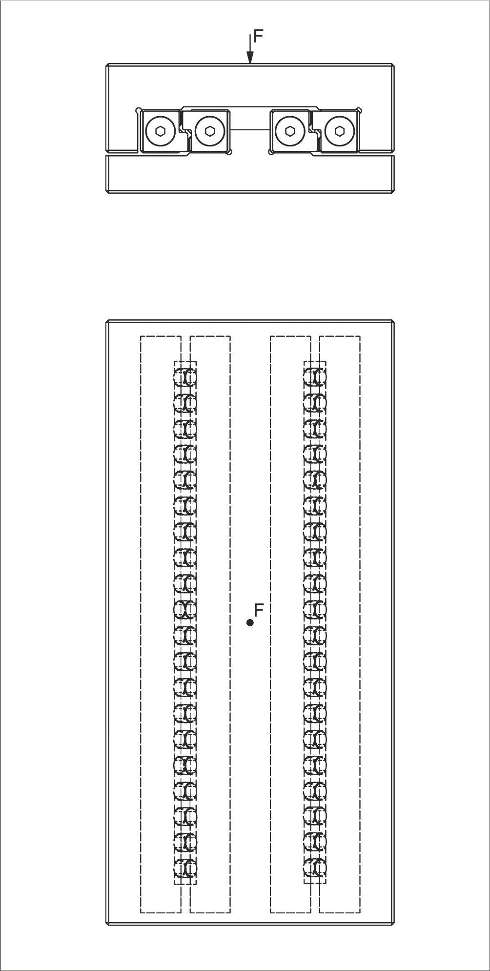
图 3:双导轨配置,负载垂直作用于系统中心
P 每个滚子的计算 (Calculation for P per roller)
P 小于 C,因此此设计是正确的。
P is smaller than C. The design is correct in this way.
符号说明 (Symbol Definitions)
| w | 从保持架起点到第一个滚动元件中心的距离 (mm) | Distance from cage start to the middle of the first rolling element in mm |
| t | 保持架分度 (mm) | Cage division in mm |
| P | 每个滚子的当量载荷 (N) | Equivalent load in N per roller |
| F | 负载 (N) | Load in N |
| C | 每个滚动元件的最大允许承载能力 (N) | Max. permissible load carrying capacity per rolling element in N |
| RA | 每个保持架的总可用滚动元件数 | Total available rolling element per cage |
| Rt | 每个保持架的负载滚动元件数 | Number of load-bearing rolling elements per cage |
范例 3:每个钢球的当量载荷 P
Example 3: Equivalent load P per ball
假设条件 (Assumption):
- 刚度保持架结构 (Rigid structure)
- 直线导轨型号 R 6 (Linear guides type R 6)
- 保持架型号 AK 6,12 个钢球 (AK 6 cage with 12 balls, RA = 12)
- 保持架分度 t = 9 mm
- 负载 F = 240 N
- 杠杆臂距离 X = 75 mm(F 到对向力的距离)
- C = 65 N(每个钢球的最大允许承载能力,根据第 5.1 章 AK 6 保持架的技术规格)
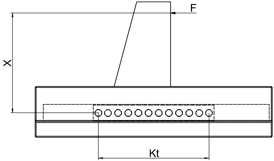
图 4:钢球保持架配置侧视图,显示偏心负载作用、负载长度 Kt 和杠杆臂距离 X
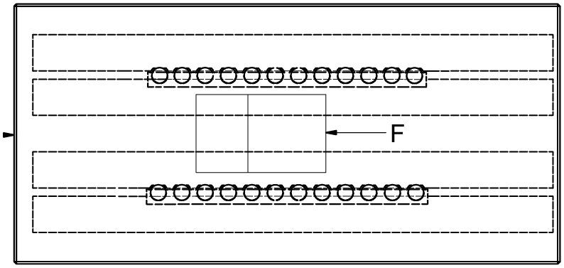
图 5:双导轨配置俯视图,显示负载 F 在两条导轨之间的作用方式
P 每个钢球的计算 (Calculation for P per ball)
P 小于 C,因此此设计是正确的。
P is smaller than C. The design is correct in this way.
符号说明 (Symbol Definitions)
| t | 保持架分度 (mm) | Cage division in mm |
| P | 每个钢球的当量载荷 (N) | Equivalent load in N per ball |
| F | 负载 (N) | Load in N |
| C | 每个滚动元件的最大允许承载能力 (N) | Max. permissible load carrying capacity per rolling element in N |
| Rtmin | 修正因子 | Correction factor |
| RA | 每个保持架的总可用滚动元件数 | Total available rolling elements per cage |
| Rt | 每个保持架的负载滚动元件数 | Number of load-bearing rolling elements per cage |
| Kt | 负载长度 (mm) | Load-bearing length in mm |
范例 4:RNG 导轨每个滚子的当量载荷 P 和合适尺寸
Example 4: Equivalent load P per roller and suitable size for RNG guideways
假设条件 (Assumption):
- RNG 型直线导轨 (RNG type linear guideway)
- 滚子保持架型号 KBN,10 个滚子 (KBN cage with 10 rollers, RA = 10)
- 负载 F = 15,000 N
- 杠杆臂距离 X = 50 mm(X 轴上的距离)
- 直线导轨中心距离 Q = 100 mm
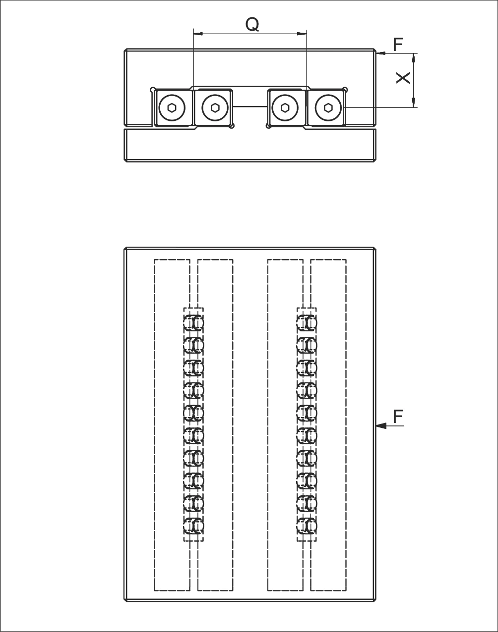
图 6:RNG 导轨双轨配置示意图,显示负载作用点与中心距离
P 每个滚子的计算 (Calculation for P per roller)
合适导轨尺寸的定义 (Definition of the suitable guideway size):
根据 KBN 保持架产品规格(第 5.2 或 5.3 章),若选择 C = 3'900 N:
According to product specification for the KBN cage (chapter 5.2 or 5.3) if C = 3'900 N were to be selected
符号说明 (Symbol Definitions)
| P (P₁, P₂) | 每个滚子的当量载荷 (N) | Equivalent loads in N per roller |
| F | 负载 (N) | Load in N |
| X | X 轴上的杠杆臂距离 (mm) | Lever arm distance on x-axis in mm |
| Q | 直线导轨的中心距离 (mm) | Medium linear guideway distance in mm |
| C | 每个滚动元件的最大允许承载能力 (N) | Max. permissible load carrying capacity per rolling element in N |
| RA | 每个保持架的总可用滚动元件数 | Total available rolling element per cage |
| Rt | 每个保持架的负载滚动元件数 | Number of load-bearing rolling elements per cage |
KBN 保持架尺寸与承载能力 (KBN Cage Dimensions and Load Capacity)
| 型号 Type | 尺寸 Size | 滚子直径 Dw (mm) | 分度 t (mm) | 宽度 w (mm) | 每个滚子承载能力 C (N) |
|---|---|---|---|---|---|
| KBN | 4 | 4.5 | 6.5 | 约 4 | 850 |
| 6 | 6.5 | 8.5 | 约 5 | 1,800 | |
| 9 | 9 | 12 | 约 7.5 | 3,900 | |
| 12 | 12 | 15 | 约 9 | 6,500 |
范例 5:每个滚针的当量载荷 P
Example 5: Equivalent load P per needle
假设条件 (Assumption):
- 直线导轨型号 N/O 2025 (Linear guideway type N/O 2025)
- 保持架型号 SHW 15,保持架长度 K = 194 mm (SHW 15 cage with length K = 194 mm)
- 保持架端部宽度 w = 2.9 mm(根据 SHW 15 保持架的技术规格)
- 滚针分度 t = 4 mm
- 负载 F = 5,000 N
- 杠杆臂距离 X = 280 mm
- 导轨中心距离 Q = 75 mm
- C = 750 N(每个滚针的最大允许承载能力,根据技术规格)
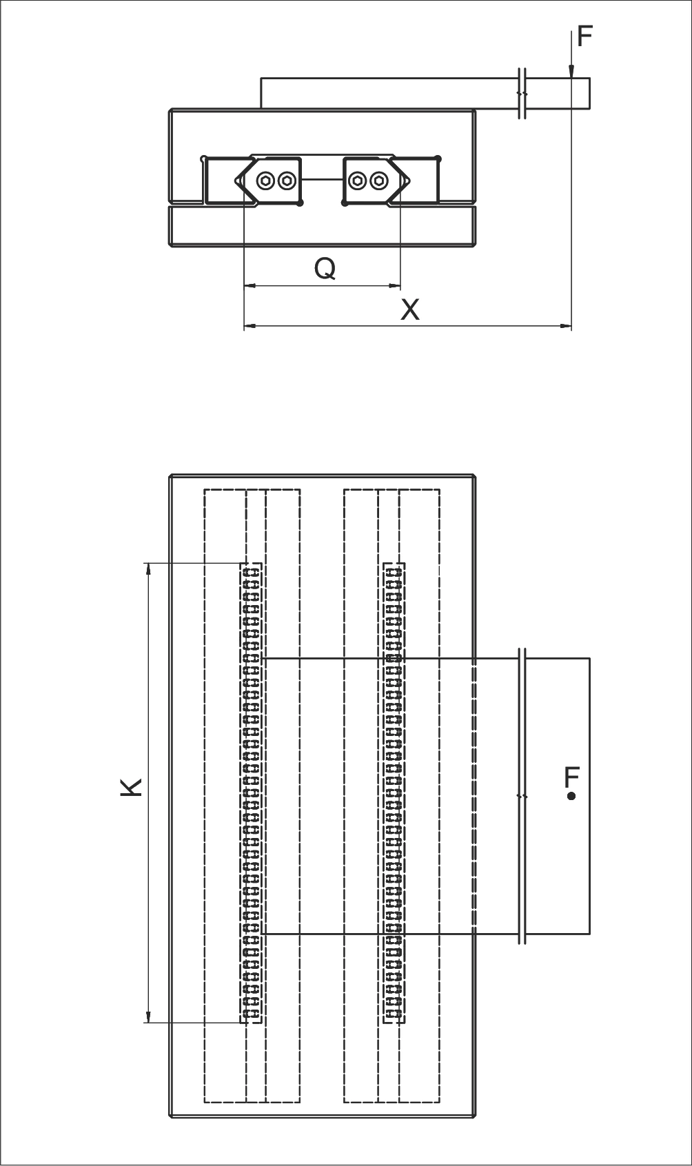
图 8:N/O 2025 滚针导轨配置示意图
P 每个滚针的计算 (Calculation for P per needle)
P 小于 C,因此此设计是正确的。
P is smaller than C. The design is correct in this way.
符号说明 (Symbol Definitions)
| w | 从保持架起点到第一个滚动元件中心的距离 (mm) | Distance from cage start to the middle of the first rolling element in mm |
| t | 保持架分度 (mm) | Cage division in mm |
| P | 每个滚针的当量载荷 (N) | Equivalent load in N per needle |
| F | 负载 (N) | Load in N |
| X | X 轴上的杠杆臂距离 (mm) | Lever arm distance on x-axis in mm |
| Q | 导轨中心距离 (mm) | Medium linear guideway distance in mm |
| C | 每个滚动元件的最大允许承载能力 (N) | Max. permissible load carrying capacity per rolling element in N |
| Rt | 每个保持架的负载滚动元件数 | Number of load-bearing rolling elements per cage |
| RA | 每个保持架的总可用滚动元件数 | Total available rolling element per cage |
| K | 保持架长度 (mm) | Cage length in mm |
范例 6:每个滚子的当量载荷 P
Example 6: Equivalent load P per roller
假设条件 (Assumption):
- 刚度结构 (Rigid structure)
- 直线导轨型号 R 12 (Linear guides type R 12)
- 保持架型号 AC 12,长度 K = 400 mm (Cage type AC 12, length K = 400 mm)
给定值:
- F = 2'000 N
- X = 500 mm
- X1 = 200 mm
- Q = 100 mm
- C = 2'500 N(见第 5.1 章 AC 12 保持架的技术规格)
- C = 2'500 N (see chapter 5.1. technical specifications for the AC 12 cage)
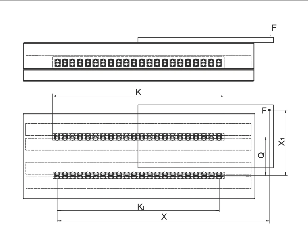
图 9:R 12 导轨与 AC 12 保持架配置示意图,显示参数 K、Kt、X、F、Q、X1
对于滚子保持架 AC 12,适用以下条件:
For the roller cage AC 12 the following applies:
计算负载长度 Kt
计算总滚子数 RA
计算负载滚子数 Rt
确定修正因子
由于 X > Kt,根据第 101 页图表:Rt/4
X > Kt = Rt/4 (according to the diagram on page 101)
计算每个滚子的当量载荷 P:
Calculation for P per roller
横向负载 (Load laterally)
纵向负载 (Load longitudinally)
总当量载荷 (Total equivalent load)
P 小于 C,因此此设计是正确的。
P is smaller than C. The design is correct in this way.
符号说明 (Symbol Definitions)
| W | 从保持架起点到第一个滚动元件中心的距离 (mm) | Distance from cage start to the middle of the first rolling element in mm |
| t | 保持架分度 (mm) | Cage division in mm |
| P | 每个滚子的当量载荷 (N) | Equivalent load in N per roller |
| F | 负载 (N) | Load in N |
| X | X 轴上的杠杆臂距离 (mm) | Lever arm distance on x-axis in mm |
| X1 | X 轴上的杠杆臂距离 1 (mm) | Lever arm distance 1 on x-axis in mm |
| Q | 直线导轨中心距离 (mm) | Medium linear guideway distance in mm |
| C | 每个滚动元件的最大允许承载能力 (N) | Max. permissible load carrying capacity per rolling element in N |
| Rt | 每个保持架的负载滚动元件数 | Number of load-bearing rolling elements per cage |
| RA | 每个保持架的总可用滚动元件数 | Total available rolling element per cage |
| K | 保持架长度 (mm) | Cage length in mm |
| Kt | 负载长度 (mm) | Load-bearing length in mm |
| ...L | 纵向 | Longitudinally |
| ...Q | 横向 | Laterally |
范例 7:循环单元的当量载荷 P
Example 7: Equivalent load P for recirculating unit
假设条件 (Assumption):
- 循环单元型号 SR 6-100 (Recirculating unit type SR 6-100)
- 直线导轨型号 R 6 (Linear guideway type R 6)
- 循环单元数量 Rt = 2(双循环单元配置)
- 负载 F = 6,000 N
- C = 2,150 N(每个循环单元的最大允许承载能力,见第 6.3 章循环单元的技术规格)
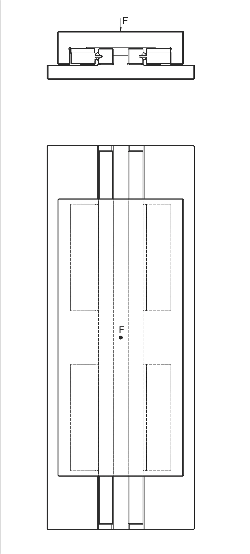
图 11:SR 6-100 循环单元双单元配置示意图
P 的计算 (Calculation for P)
P 小于 C,因此此设计是正确的。
P is smaller than C. The design is correct in this way.
符号说明 (Symbol Definitions)
| P | 当量载荷 (N) | Equivalent loads in N |
| F | 负载 (N) | Load in N |
| C | 最大允许承载能力 (N) | Max. permissible load carrying capacity in N |
| Rt | 负载循环单元数量 | Number of load-bearing recirculating units |
范例 8:纵向和横向的力矩载荷 M
Example 8: Moment load M longitudinally and laterally
假设条件 (Assumption):
- 循环单元型号 SR 6-150 (Recirculating unit type SR 6-150)
- 直线导轨型号 RD 6 (Linear guideway type RD 6)
- 负载 F = 2,000 N
- 力臂距离 X = 45 mm(负载作用点到对向力的距离)
- ML = 112 Nm(允许的纵向和横向力矩载荷,根据第 6.3 章循环单元的技术规格)
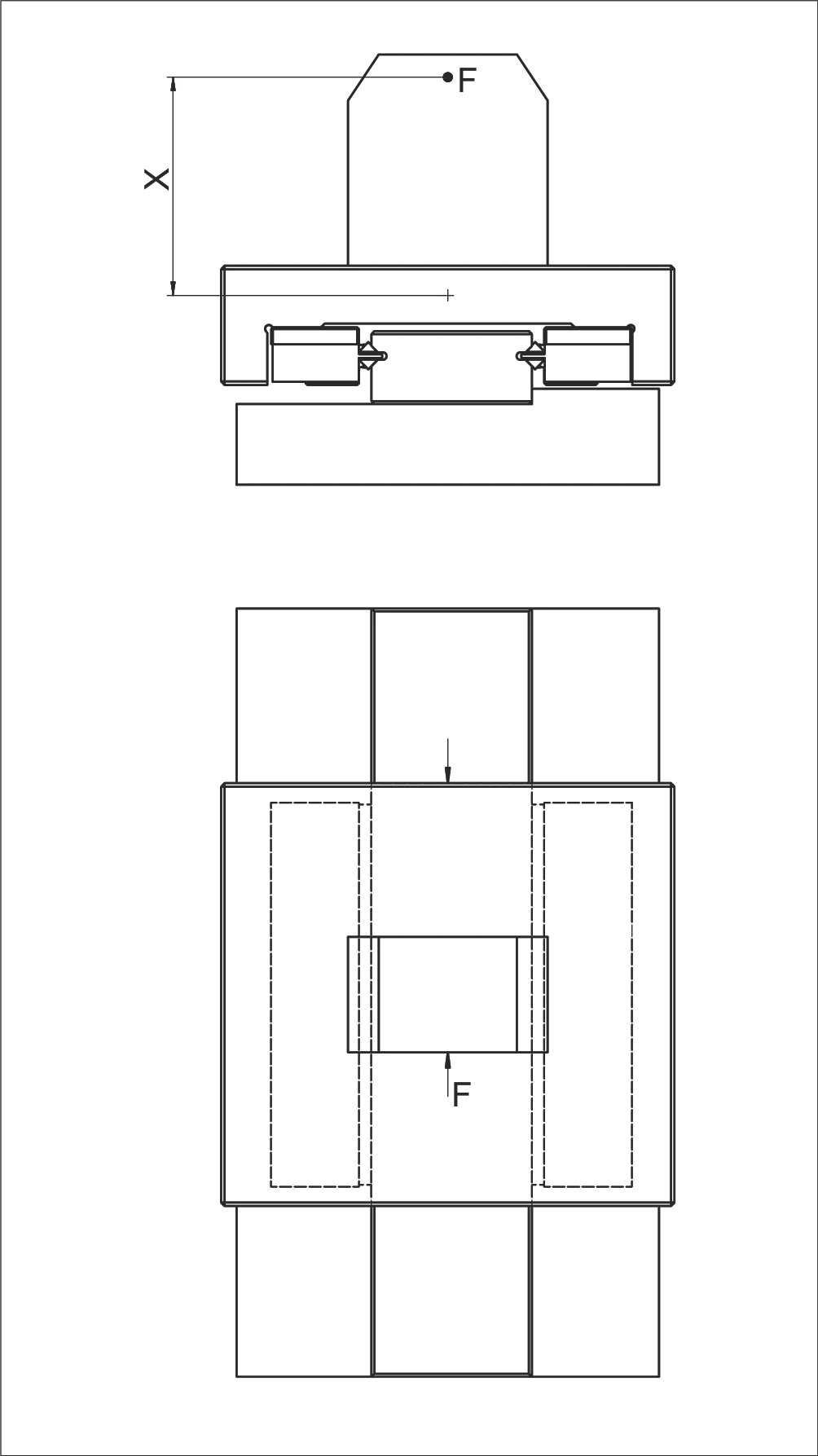
图 12:循环单元力矩载荷配置示意图(显示力 F 和力臂 X)
M 的计算 (Calculation for M)
力矩载荷 M 低于允许负载 ML,因此此设计是正确的。
The moment load M is below the permissible load ML. Thus the design is correct.
符号说明 (Symbol Definitions)
| M | 纵向和横向力矩载荷 (Nm) | Moment load in Nm longitudinally and laterally |
| ML | 允许的纵向和横向力矩载荷 (Nm) | Permitted moment load in Nm longitudinally and laterally |
| X | 距离 (mm) | distance in mm |
| F | 负载 (N) | load in N |
范例 9:当量载荷 PL 和 PQ
Example 9: Equivalent loads PL and PQ
假设条件 (Assumption):
- 循环单元型号 NRT 26 111(顶部)(Recirculating unit type NRT 26 111 (top))
- 循环单元型号 NRT 19 077(底部和侧面)(Recirculating unit type NRT 19 077 (bottom and side))
给定值:
- C = 98'000 N(顶部循环单元)(top recirculating unit)
- C = 43'000 N(底部和侧面循环单元)(bottom and side recirculating units)
- K = 700 mm
- K1 = 450 mm
- Rtmin = 0.5
- F = 83'000 N
- X = 500 mm
- Y = 100 mm
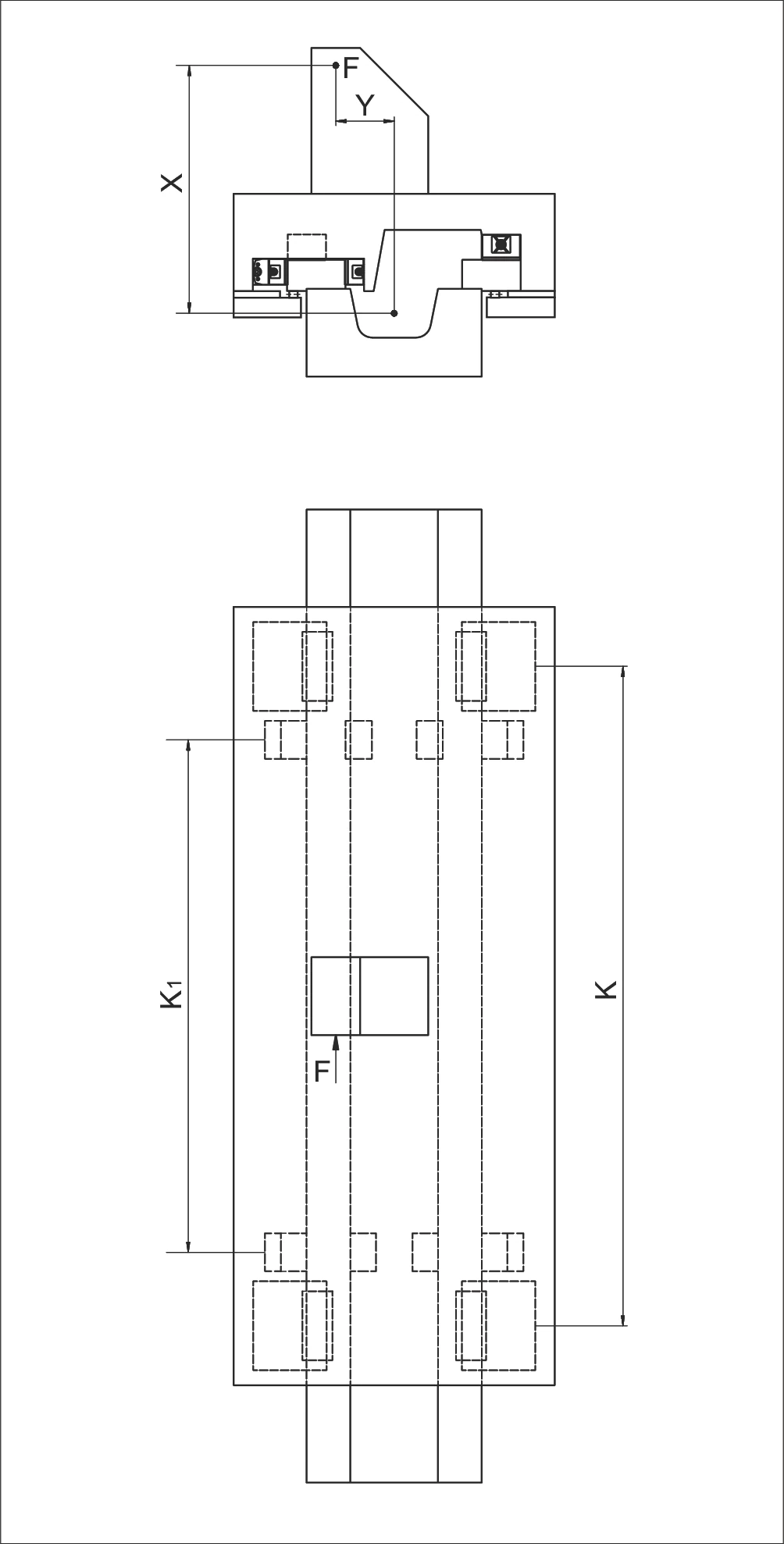
图 13:NRT 26 111 和 NRT 19 077 循环单元配置示意图
PL 与 PQ 的计算 (Calculation for PL and PQ)
纵向负载 (Load longitudinally)
横向负载 (Load laterally)
| 符号 | 说明(单位) | English Description |
|---|---|---|
| P | 当量载荷 (N) | Equivalent load in N |
| PL | 纵向当量载荷 (N) | Equivalent load longitudinally in N |
| PQ | 横向当量载荷 (N) | Equivalent load laterally in N |
| F | 负载 (N) | load in N |
| X | 距离 (mm) | distance in mm |
| Y | 距离 (mm) | distance in mm |
| C | 每个循环单元的最大允许承载能力 (N) | Max. permissible load carrying capacity per recirculating unit in N |
| Rtmin | 修正因子 | Correction factor |
| K | 循环单元间距 (mm) | Spacing between the recirculating units in mm |
| K1 | 循环单元间距 (mm) | Spacing between the recirculating units in mm |