The following example calculations illustrate the procedure for some typical problems.
Example 1: Equivalent load P per roller
Load and design verification
Assumption:
Input parameters
- Linear guides type R 6
- AC 6 cage with 8 rollers (= RA)
- F = 350 N
- X = 120 mm
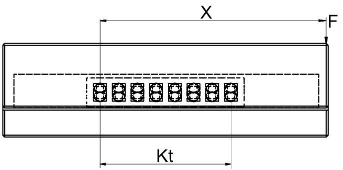
Example 1 diagram – single guideway configuration
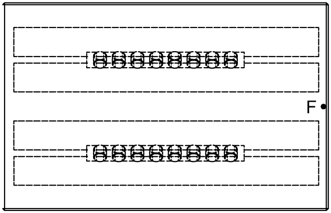
Example 1 diagram – dual guideway top view
For the roller cage type AC 6 the following applies:
Cage-specific parameters
Calculation for P per roller
Load equation and result
P is smaller than C. The design is correct in this way.
Design verification passed.
Note:
Load component annotation
The asymmetric distribution of force is most safely taken into account when the load on the number of load bearing rolling elements (Rtmin) for the guideway is reduced.
Design guidance note
Symbol definitions
| P | Equivalent load in N per roller | Equivalent load in N per roller |
| F | load in N | load in N |
| C | Max. permissible load carrying capacity per rolling element in N | Max. permissible load carrying capacity per rolling element in N |
| X | Lever arm distance on x-axis in mm | Lever arm distance on x-axis in mm |
| RA | Total available rolling element per cage | Total available rolling element per cage |
| Rtmin | Correction factor | Correction factor |
| t | cage division in mm | cage division in mm |
| Kt | Load-bearing length in mm | Load-bearing length in mm |
Example 2: Equivalent load P per roller
Load and design verification
Assumption:
Input parameters
- Linear guides type R 6
- Roller cage type AC 6 cage with 20 rollers (= RA)
- F = 6'500 N
- C = 530 N (per chapter 5.1 techn. specifications of AC 6 cage)
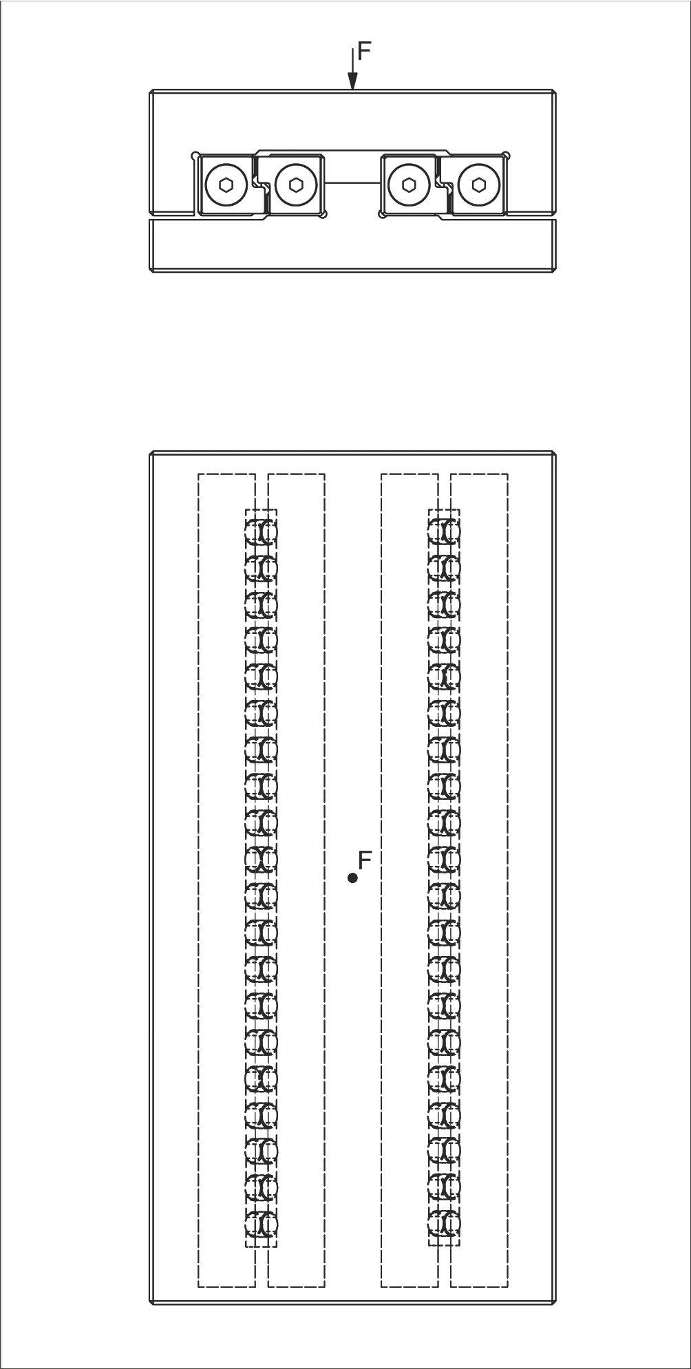
Example 2 diagram – dual guideway configuration
Calculation for P per roller
Load equation and result
P is smaller than C. The design is correct in this way.
Design verification passed.
Symbol definitions
| w | Distance from cage start to the middle of the first rolling element in mm | Distance from cage start to the middle of the first rolling element in mm |
| t | cage division in mm | cage division in mm |
| P | Equivalent load in N per roller | Equivalent load in N per roller |
| F | load in N | load in N |
| C | Max. permissible load carrying capacity per rolling element in N | Max. permissible load carrying capacity per rolling element in N |
| RA | Total available rolling element per cage | Total available rolling element per cage |
| Rt | Number of load-bearing rolling elements per cage | Number of load-bearing rolling elements per cage |
Example 3: Equivalent load P per ball
Load and design verification
Assumption:
Input parameters
- Rigid slide structure
- Linear guides type R 6
- Cage type AK 6 with 12 balls (= RA); t = 9 mm (according to chapter 5.1, technical data for the AK 6 cage)
- F = 240 N
- X = 75 mm (distance F to opposing force)
- C = 65 N (according to chapter 5.1, technical data for the AK 6 cage)
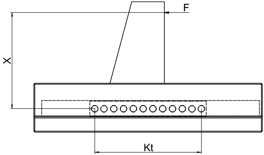
Example 3 ball cage side view
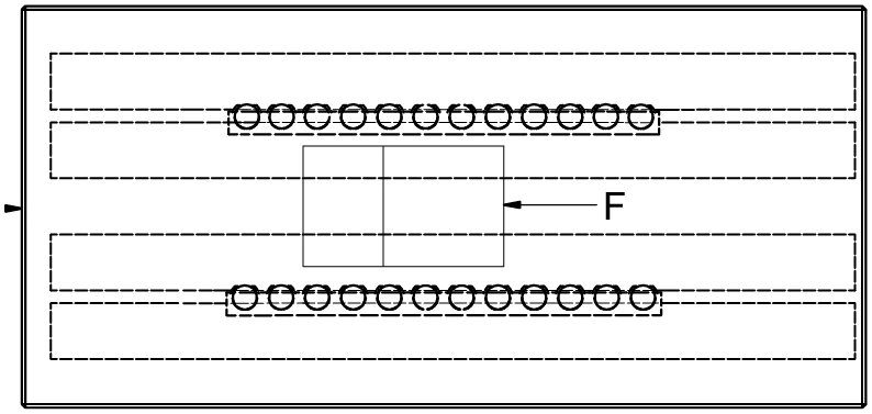
Example 3 dual guideway top view
Calculation for P per ball
Load equation and result
P is smaller than C. The design is correct in this way.
Design verification passed.
Symbol definitions
| t | cage division in mm | cage division in mm |
| P | Equivalent load in N per ball | Equivalent load in N per ball |
| F | load in N | load in N |
| C | Max. permissible load carrying capacity per rolling element in N | Max. permissible load carrying capacity per rolling element in N |
| Rtmin | Correction factor | Correction factor |
| RA | Total available rolling elements per cage | Total available rolling elements per cage |
| Rt | Number of load-bearing rolling elements per cage | Number of load-bearing rolling elements per cage |
| Kt | Load-bearing length in mm | Load-bearing length in mm |
Example 4: Equivalent load P per roller and the suitable size for RNG guideways
Load and design verification
Assumption:
Input parameters
- Type RNG linear guideways
- Roller cage type KBN with 10 rollers (RA)
- F = 15'000 N
- X = 50 mm
- Q = 100 mm
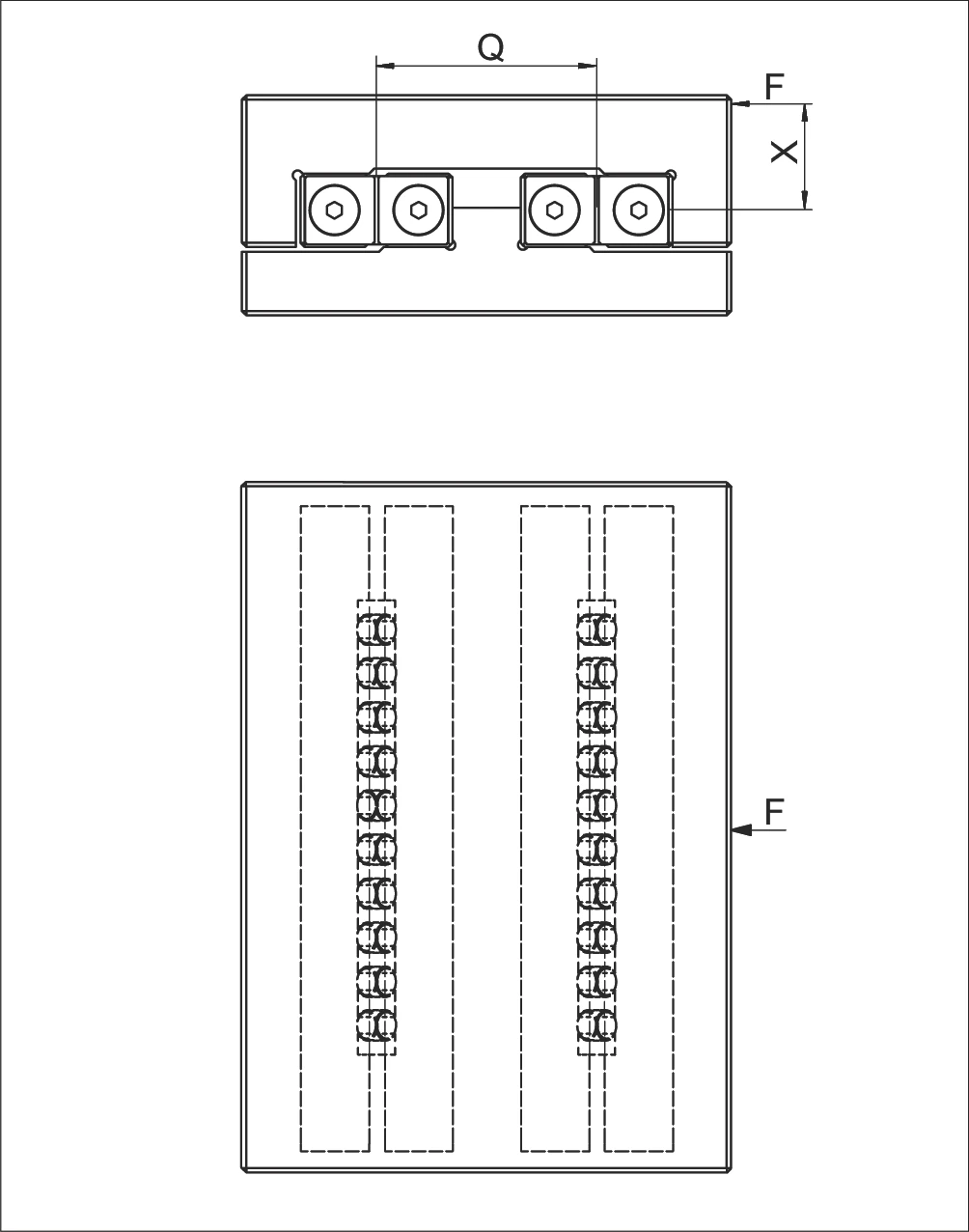
Example 4 RNG guideway configuration
Calculation for P per roller
Load equation and result
Definition of the suitable guideway size:
Size selection criterion
According to product specification for the KBN cage (chapter 5.2 or 5.3) if C = 3'900 N were to be selected.
The roller size 9 is suitable. Thus select cage KBN 9 and the linear guideway RNG 9, provided the service life has been fulfilled.
Symbol definitions
| P (P1, P2) | Equivalent loads in N per roller | Equivalent loads in N per roller |
| F | load in N | load in N |
| X | Lever arm distance on x-axis in mm | Lever arm distance on x-axis in mm |
| Q | Medium linear guideway distance in mm | Medium linear guideway distance in mm |
| C | Max. permissible load carrying capacity per rolling element in N | Max. permissible load carrying capacity per rolling element in N |
| RA | Total available rolling element per cage | Total available rolling element per cage |
| Rt | Number of load-bearing rolling elements per cage | Number of load-bearing rolling elements per cage |
KBN cage dimensions and load capacity
| Type | Size | Dw (mm) | t (mm) | w (mm) | C per roller (N) |
|---|---|---|---|---|---|
| KBN | 4 | 4.5 | 6.5 | approx. 4 | 850 |
| 6 | 6.5 | 8.5 | approx. 5 | 1'800 | |
| 9 | 9 | 12 | approx. 7.5 | 3'900 | |
| 12 | 12 | 15 | approx. 9 | 6'500 |
Example 5: Equivalent load P per needle
Load and design verification
Assumption:
Input parameters
- Linear guideways type N/O 2025
- SHW 15 cage, cage length K = 194 mm (w = 2.9 mm according to techn. specifications of the SHW 15 cage)
- t = 4 mm
- F = 5'000 N
- X = 280 mm
- Q = 75 mm
- C = 750 N (according to techn. specifications for the AC 15 cage)
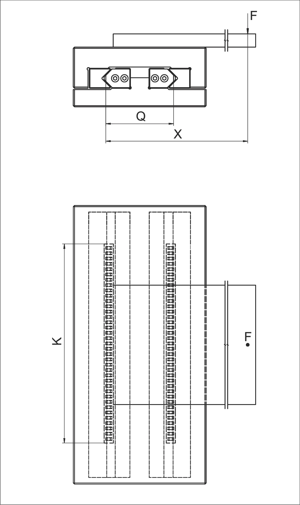
Example 5 N/O 2025 needle guideway configuration
Calculation for P per needle
Load equation and result
P is smaller than C. The design is correct in this way.
Design verification passed.
Symbol definitions
| w | Distance from cage start to the middle of the first rolling element in mm | Distance from cage start to the middle of the first rolling element in mm |
| t | cage division in mm | cage division in mm |
| P | Equivalent load in N per needle | Equivalent load in N per needle |
| F | load in N | load in N |
| X | Lever arm distance on x-axis in mm | Lever arm distance on x-axis in mm |
| Q | Medium linear guideway distance in mm | Medium linear guideway distance in mm |
| C | Max. permissible load carrying capacity per rolling element in N | Max. permissible load carrying capacity per rolling element in N |
| Rt | Number of load-bearing rolling elements per cage | Number of load-bearing rolling elements per cage |
| RA | Total available rolling element per cage | Total available rolling element per cage |
| K | Cage length in mm | Cage length in mm |
Example 6: Equivalent load P per roller
Load and design verification
Assumption:
Input parameters
- Rigid structure
- Linear guides type R 12
- Cage type AC 12, length K = 400 mm
- F = 2'000 N
- X = 500 mm
- X1 = 200 mm
- Q = 100 mm
- C = 2'500 N (see chapter 5.1, technical specifications for the AC 12 cage)
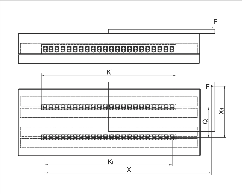
Example 6 R 12 configuration with AC 12 cage
For the roller cage AC 12 the following applies:
Cage-specific parameters
Calculation for P per roller
Calculation step
Load laterally
Directional load component
Load longitudinally
Directional load component
P is smaller than C. The design is correct in this way.
Design verification passed.
Symbol definitions
| w | Distance from cage start to the middle of the first rolling element in mm | Distance from cage start to the middle of the first rolling element in mm |
| t | cage division in mm | cage division in mm |
| P | Equivalent load in N per roller | Equivalent load in N per roller |
| F | load in N | load in N |
| X | Lever arm distance on x-axis in mm | Lever arm distance on x-axis in mm |
| X1 | Lever arm distance 1 on x-axis in mm | Lever arm distance 1 on x-axis in mm |
| Q | Medium linear guideway distance in mm | Medium linear guideway distance in mm |
| C | Max. permissible load carrying capacity per rolling element in N | Max. permissible load carrying capacity per rolling element in N |
| Rt | Number of load-bearing rolling elements per cage | Number of load-bearing rolling elements per cage |
| RA | Total available rolling element per cage | Total available rolling element per cage |
| K | Cage length in mm | Cage length in mm |
| Kt | Load-bearing length in mm | Load-bearing length in mm |
| ...L | Longitudinally | Longitudinally |
| ...Q | Laterally | Laterally |
Example 7: Equivalent load P for recirculating unit
Load and design verification
Assumption:
Input parameters
- Recirculating unit type SR 6-100
- Linear guides type R 6
- Rt = 2 recirculating unit
- F = 6'000 N
- C = 2'150 N (see chapter 6.3, technical specifications for the recirculating unit)
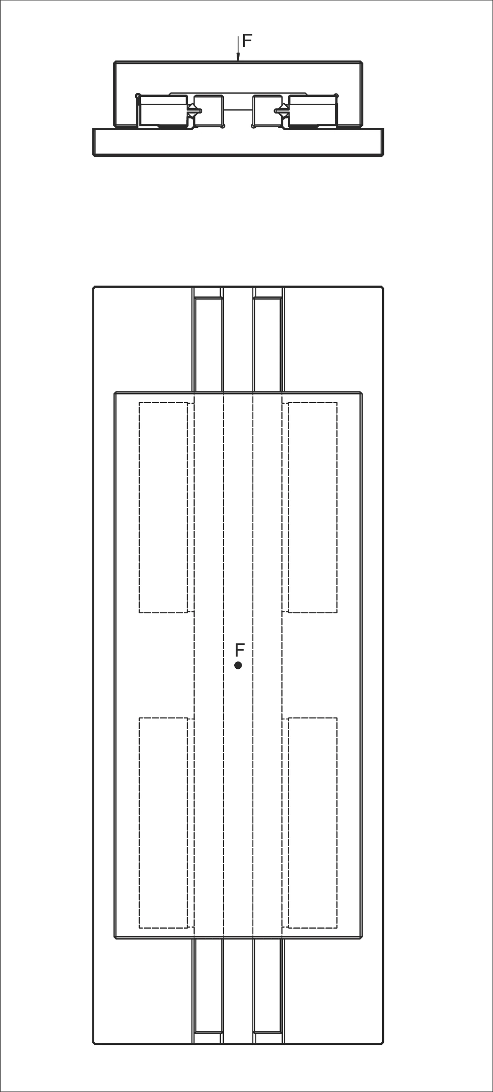
Example 7 SR 6-100 recirculating unit configuration
Calculation for P
Calculation step
P is smaller than C. The design is correct in this way.
Design verification passed.
Symbol definitions
| P | Equivalent loads in N | Equivalent loads in N |
| F | load in N | load in N |
| C | Max. permissible load carrying capacity in N | Max. permissible load carrying capacity in N |
| Rt | Number of load-bearing recirculating units | Number of load-bearing recirculating units |
Example 8: Moment load M longitudinally and laterally
Load and design verification
Assumption:
Input parameters
- Recirculating unit type SR 6-150
- Linear guideways type RD 6
- ML = 112 Nm (according to chapter 6.3, technical specifications for the recirculating unit)
- X = 45 mm (distance F to opposing force)
- F = 2'000 N
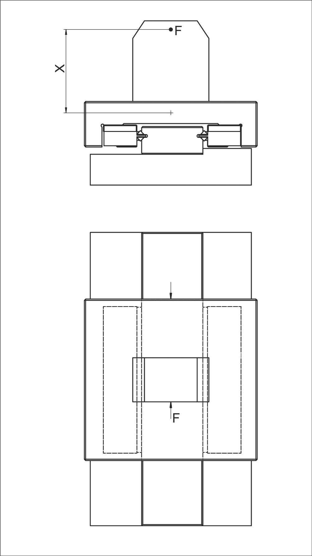
Example 8 moment load configuration
Calculation for M
Calculation step
The moment load M is below the permissible load ML. Thus the design is correct.
Symbol definitions
| M | Moment load in Nm longitudinally and laterally | Moment load in Nm longitudinally and laterally |
| ML | Permitted moment load in Nm longitudinally and laterally | Permitted moment load in Nm longitudinally and laterally |
| X | distance in mm | distance in mm |
| F | load in N | load in N |
Example 9: Equivalent loads PL and PQ
Load and design verification
Assumption:
Input parameters
- Recirculating unit top type NRT 26 111 (C = 98'000 N)
- Recirculating unit bottom type NRT 19 077 (C = 43'000 N)
- Recirculating unit side type NRT 19 077 (C = 43'000 N)
- K = 700 mm
- K1 = 450 mm
- Rtmin = 0.5 (according to table on page 101)
- F = 83'000 N
- X = 500 mm
- Y = 100 mm
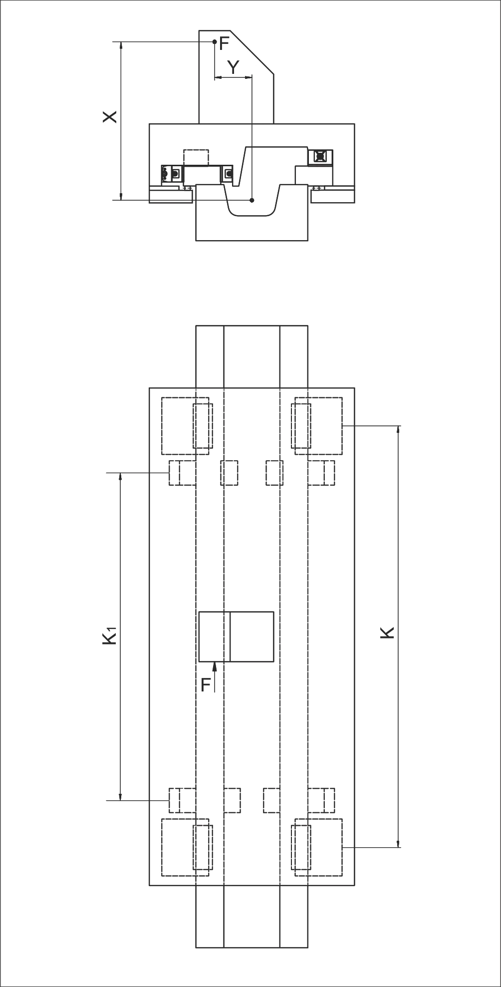
Example 9 NRT recirculating unit configuration
Calculation for PL and PQ
Load longitudinally
Directional load component
Load laterally
Directional load component
Symbol definitions
| Symbol | Description (unit) | Detail |
|---|---|---|
| P | Equivalent load in N | Equivalent load in N |
| PL | Equivalent load longitudinally in N | Equivalent load longitudinally in N |
| PQ | Equivalent load laterally in N | Equivalent load laterally in N |
| F | load in N | load in N |
| X | distance in mm | distance in mm |
| Y | distance in mm | distance in mm |
| C | Max. permissible load carrying capacity per recirculating unit in N | Max. permissible load carrying capacity per recirculating unit in N |
| Rtmin | Correction factor | Correction factor |
| K | Spacing between the recirculating units in mm | Spacing between the recirculating units in mm |
| K1 | Spacing between the recirculating units in mm | Spacing between the recirculating units in mm |