以下計算範例說明了一些典型問題的處理程序。
範例 1:每個滾柱的等效負載 P
Example 1: Equivalent load P per roller
假設條件 (Assumption):
- 線性導軌型號 R 6 (Linear guides type R 6)
- AC 6 保持器,8 個滾柱 (AC 6 cage with 8 rollers, RA = 8)
- 負載 F = 350 N
- 槓桿臂距離 X = 120 mm
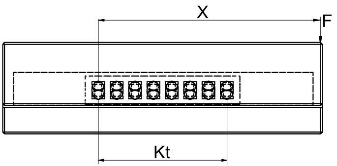
圖 1:單導軌配置的力學模型,顯示負載 F、槓桿臂距離 X 和負載長度 Kt
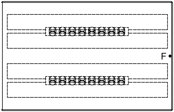
圖 2:雙導軌配置的俯視圖,顯示力的分布
對於 AC 6 型滾柱保持器,適用以下條件:
For the roller cage type AC 6 the following applies:
P 每個滾柱的計算 (Calculation for P per roller)
P 小於 C,因此此設計是正確的。
P is smaller than C. The design is correct in this way.
注意:
力的非對稱分布最安全的考慮方式是減少導軌的負載滾動元件數量 (Rtmin)。
The asymmetric distribution of force is most safely taken into account when the load on the number of load bearing rolling elements (Rtmin) for the guideway is reduced.
符號說明 (Symbol Definitions)
| P | 每個滾柱的等效負載 (N) | Equivalent load in N per roller |
| F | 負載 (N) | Load in N |
| C | 每個滾動元件的最大允許負載能力 (N) | Max. permissible load carrying capacity per rolling element in N |
| X | X 軸上的槓桿臂距離 (mm) | Lever arm distance on x-axis in mm |
| RA | 每個保持器的總可用滾動元件數 | Total available rolling element per cage |
| Rtmin | 修正因子 | Correction factor |
| t | 保持器分度 (mm) | Cage division in mm |
| Kt | 負載長度 (mm) | Load-bearing length in mm |
範例 2:每個滾柱的等效負載 P(20 個滾柱)
Example 2: Equivalent load P per roller (20 rollers)
假設條件 (Assumption):
- 線性導軌型號 R 6 (Linear guides type R 6)
- 滾柱保持器型號 AC 6,20 個滾柱 (AC 6 cage with 20 rollers, RA = 20)
- 負載 F = 6,500 N(垂直作用於雙導軌系統)
- C = 530 N(每個滾柱的最大允許負載能力,根據第 5.1 章 AC 6 保持器的技術規格)
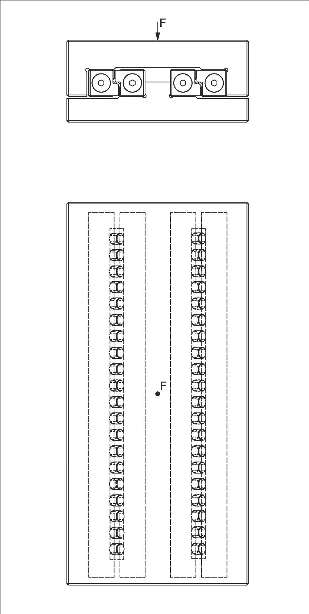
圖 3:雙導軌配置,負載垂直作用於系統中心
P 每個滾柱的計算 (Calculation for P per roller)
P 小於 C,因此此設計是正確的。
P is smaller than C. The design is correct in this way.
符號說明 (Symbol Definitions)
| w | 從保持器起點到第一個滾動元件中心的距離 (mm) | Distance from cage start to the middle of the first rolling element in mm |
| t | 保持器分度 (mm) | Cage division in mm |
| P | 每個滾柱的等效負載 (N) | Equivalent load in N per roller |
| F | 負載 (N) | Load in N |
| C | 每個滾動元件的最大允許負載能力 (N) | Max. permissible load carrying capacity per rolling element in N |
| RA | 每個保持器的總可用滾動元件數 | Total available rolling element per cage |
| Rt | 每個保持器的負載滾動元件數 | Number of load-bearing rolling elements per cage |
範例 3:每個滾珠的等效負載 P
Example 3: Equivalent load P per ball
假設條件 (Assumption):
- 剛性保持器結構 (Rigid structure)
- 線性導軌型號 R 6 (Linear guides type R 6)
- 保持器型號 AK 6,12 個滾珠 (AK 6 cage with 12 balls, RA = 12)
- 保持器分度 t = 9 mm
- 負載 F = 240 N
- 槓桿臂距離 X = 75 mm(F 到對向力的距離)
- C = 65 N(每個滾珠的最大允許負載能力,根據第 5.1 章 AK 6 保持器的技術規格)
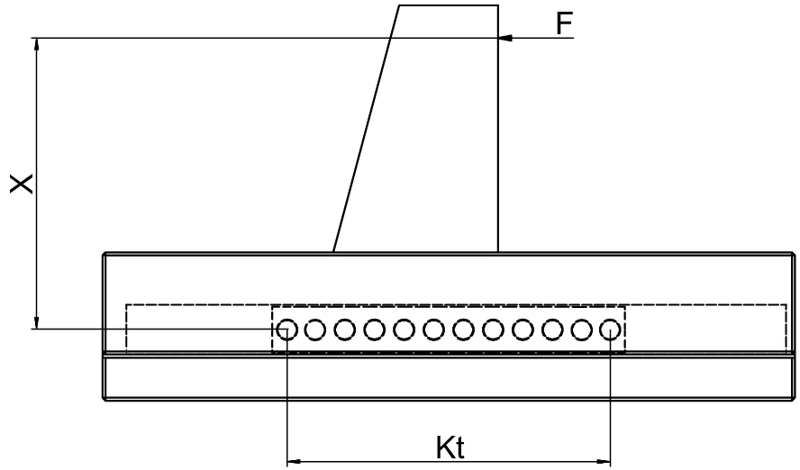
圖 4:滾珠保持器配置側視圖,顯示偏心負載作用、負載長度 Kt 和槓桿臂距離 X
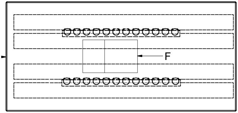
圖 5:雙導軌配置俯視圖,顯示負載 F 在兩條導軌之間的作用方式
P 每個滾珠的計算 (Calculation for P per ball)
P 小於 C,因此此設計是正確的。
P is smaller than C. The design is correct in this way.
符號說明 (Symbol Definitions)
| t | 保持器分度 (mm) | Cage division in mm |
| P | 每個滾珠的等效負載 (N) | Equivalent load in N per ball |
| F | 負載 (N) | Load in N |
| C | 每個滾動元件的最大允許負載能力 (N) | Max. permissible load carrying capacity per rolling element in N |
| Rtmin | 修正因子 | Correction factor |
| RA | 每個保持器的總可用滾動元件數 | Total available rolling elements per cage |
| Rt | 每個保持器的負載滾動元件數 | Number of load-bearing rolling elements per cage |
| Kt | 負載長度 (mm) | Load-bearing length in mm |
範例 4:RNG 導軌每個滾柱的等效負載 P 和合適尺寸
Example 4: Equivalent load P per roller and suitable size for RNG guideways
假設條件 (Assumption):
- RNG 型線性導軌 (RNG type linear guideway)
- 滾柱保持器型號 KBN,10 個滾柱 (KBN cage with 10 rollers, RA = 10)
- 負載 F = 15,000 N
- 槓桿臂距離 X = 50 mm(X 軸上的距離)
- 線性導軌中心距離 Q = 100 mm
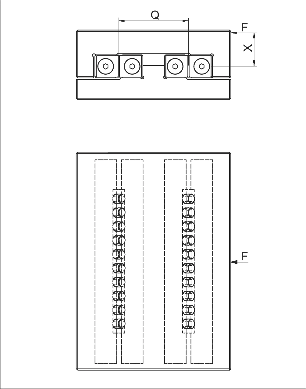
圖 6:RNG 導軌雙軌配置示意圖,顯示負載作用點與中心距離
P 每個滾柱的計算 (Calculation for P per roller)
合適導軌尺寸的定義 (Definition of the suitable guideway size):
根據 KBN 保持器產品規格(第 5.2 或 5.3 章),若選擇 C = 3'900 N:
According to product specification for the KBN cage (chapter 5.2 or 5.3) if C = 3'900 N were to be selected
符號說明 (Symbol Definitions)
| P (P₁, P₂) | 每個滾柱的等效負載 (N) | Equivalent loads in N per roller |
| F | 負載 (N) | Load in N |
| X | X 軸上的槓桿臂距離 (mm) | Lever arm distance on x-axis in mm |
| Q | 線性導軌的中心距離 (mm) | Medium linear guideway distance in mm |
| C | 每個滾動元件的最大允許負載能力 (N) | Max. permissible load carrying capacity per rolling element in N |
| RA | 每個保持器的總可用滾動元件數 | Total available rolling element per cage |
| Rt | 每個保持器的負載滾動元件數 | Number of load-bearing rolling elements per cage |
KBN 保持器尺寸與負載能力 (KBN Cage Dimensions and Load Capacity)
| 型號 Type | 尺寸 Size | 滾柱直徑 Dw (mm) | 分度 t (mm) | 寬度 w (mm) | 每個滾柱負載能力 C (N) |
|---|---|---|---|---|---|
| KBN | 4 | 4.5 | 6.5 | 約 4 | 850 |
| 6 | 6.5 | 8.5 | 約 5 | 1,800 | |
| 9 | 9 | 12 | 約 7.5 | 3,900 | |
| 12 | 12 | 15 | 約 9 | 6,500 |
範例 5:每個滾針的等效負載 P
Example 5: Equivalent load P per needle
假設條件 (Assumption):
- 線性導軌型號 N/O 2025 (Linear guideway type N/O 2025)
- 保持器型號 SHW 15,保持器長度 K = 194 mm (SHW 15 cage with length K = 194 mm)
- 保持器端部寬度 w = 2.9 mm(根據 SHW 15 保持器的技術規格)
- 滾針分度 t = 4 mm
- 負載 F = 5,000 N
- 槓桿臂距離 X = 280 mm
- 導軌中心距離 Q = 75 mm
- C = 750 N(每個滾針的最大允許負載能力,根據技術規格)
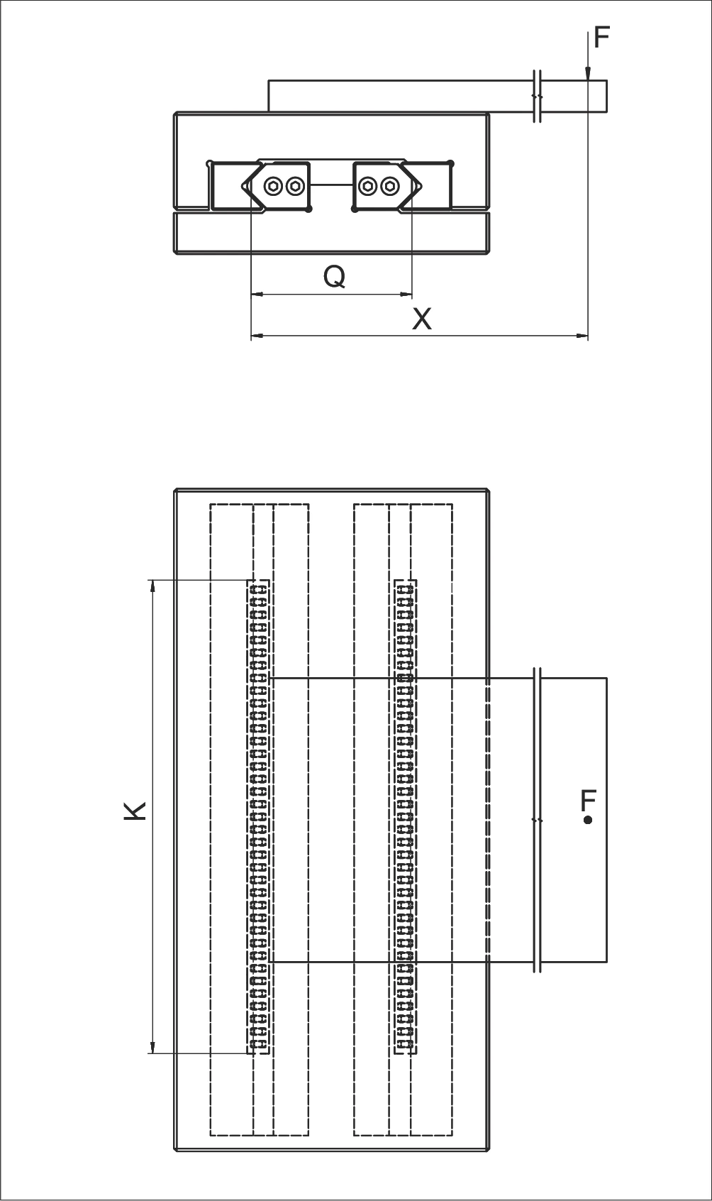
圖 8:N/O 2025 滾針導軌配置示意圖
P 每個滾針的計算 (Calculation for P per needle)
P 小於 C,因此此設計是正確的。
P is smaller than C. The design is correct in this way.
符號說明 (Symbol Definitions)
| w | 從保持器起點到第一個滾動元件中心的距離 (mm) | Distance from cage start to the middle of the first rolling element in mm |
| t | 保持器分度 (mm) | Cage division in mm |
| P | 每個滾針的等效負載 (N) | Equivalent load in N per needle |
| F | 負載 (N) | Load in N |
| X | X 軸上的槓桿臂距離 (mm) | Lever arm distance on x-axis in mm |
| Q | 導軌中心距離 (mm) | Medium linear guideway distance in mm |
| C | 每個滾動元件的最大允許負載能力 (N) | Max. permissible load carrying capacity per rolling element in N |
| Rt | 每個保持器的負載滾動元件數 | Number of load-bearing rolling elements per cage |
| RA | 每個保持器的總可用滾動元件數 | Total available rolling element per cage |
| K | 保持器長度 (mm) | Cage length in mm |
範例 6:每個滾柱的等效負載 P
Example 6: Equivalent load P per roller
假設條件 (Assumption):
- 剛性結構 (Rigid structure)
- 線性導軌型號 R 12 (Linear guides type R 12)
- 保持器型號 AC 12,長度 K = 400 mm (Cage type AC 12, length K = 400 mm)
給定值:
- F = 2'000 N
- X = 500 mm
- X1 = 200 mm
- Q = 100 mm
- C = 2'500 N(見第 5.1 章 AC 12 保持器的技術規格)
- C = 2'500 N (see chapter 5.1. technical specifications for the AC 12 cage)
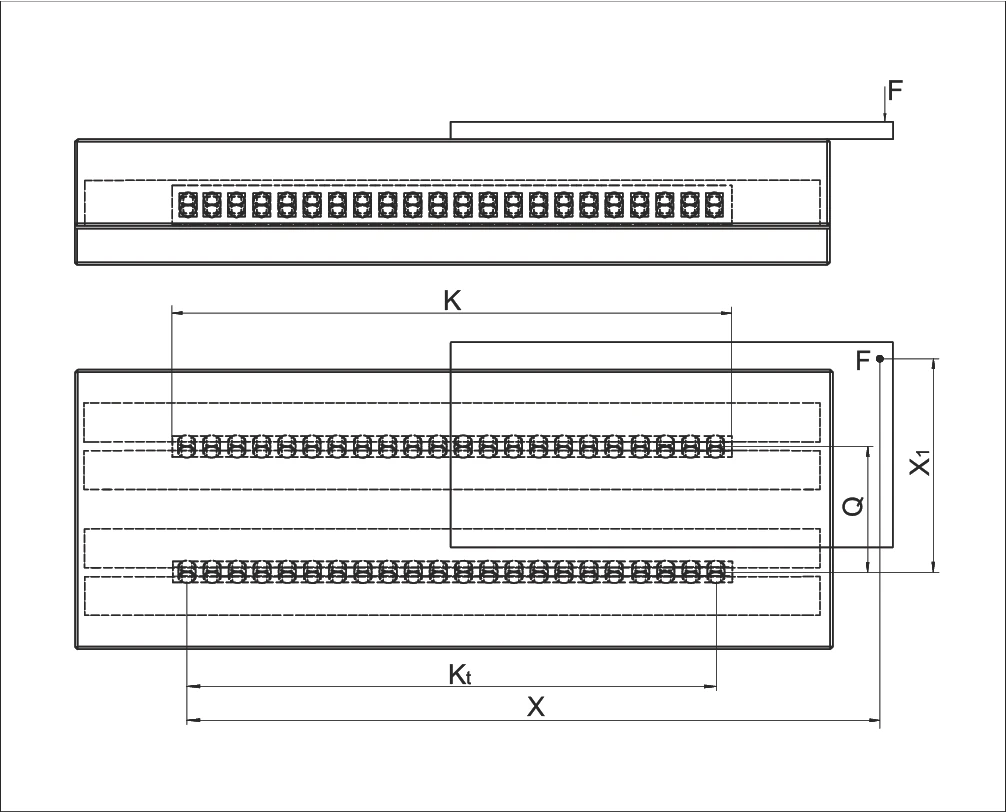
圖 9:R 12 導軌與 AC 12 保持器配置示意圖,顯示參數 K、Kt、X、F、Q、X1
對於滾柱保持器 AC 12,適用以下條件:
For the roller cage AC 12 the following applies:
計算負載長度 Kt
計算總滾柱數 RA
計算負載滾柱數 Rt
確定修正因子
由於 X > Kt,根據第 101 頁圖表:Rt/4
X > Kt = Rt/4 (according to the diagram on page 101)
計算每個滾柱的等效負載 P:
Calculation for P per roller
橫向負載 (Load laterally)
縱向負載 (Load longitudinally)
總等效負載 (Total equivalent load)
P 小於 C,因此此設計是正確的。
P is smaller than C. The design is correct in this way.
符號說明 (Symbol Definitions)
| W | 從保持器起點到第一個滾動元件中心的距離 (mm) | Distance from cage start to the middle of the first rolling element in mm |
| t | 保持器分度 (mm) | Cage division in mm |
| P | 每個滾柱的等效負載 (N) | Equivalent load in N per roller |
| F | 負載 (N) | Load in N |
| X | X 軸上的槓桿臂距離 (mm) | Lever arm distance on x-axis in mm |
| X1 | X 軸上的槓桿臂距離 1 (mm) | Lever arm distance 1 on x-axis in mm |
| Q | 線性導軌中心距離 (mm) | Medium linear guideway distance in mm |
| C | 每個滾動元件的最大允許負載能力 (N) | Max. permissible load carrying capacity per rolling element in N |
| Rt | 每個保持器的負載滾動元件數 | Number of load-bearing rolling elements per cage |
| RA | 每個保持器的總可用滾動元件數 | Total available rolling element per cage |
| K | 保持器長度 (mm) | Cage length in mm |
| Kt | 負載長度 (mm) | Load-bearing length in mm |
| ...L | 縱向 | Longitudinally |
| ...Q | 橫向 | Laterally |
範例 7:循環單元的等效負載 P
Example 7: Equivalent load P for recirculating unit
假設條件 (Assumption):
- 循環單元型號 SR 6-100 (Recirculating unit type SR 6-100)
- 線性導軌型號 R 6 (Linear guideway type R 6)
- 循環單元數量 Rt = 2(雙循環單元配置)
- 負載 F = 6,000 N
- C = 2,150 N(每個循環單元的最大允許負載能力,見第 6.3 章循環單元的技術規格)
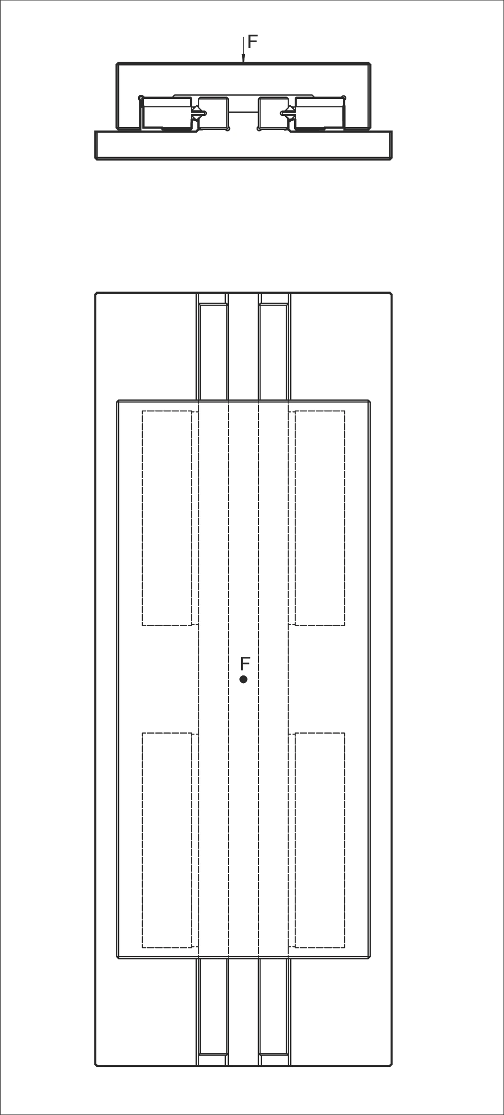
圖 11:SR 6-100 循環單元雙單元配置示意圖
P 的計算 (Calculation for P)
P 小於 C,因此此設計是正確的。
P is smaller than C. The design is correct in this way.
符號說明 (Symbol Definitions)
| P | 等效負載 (N) | Equivalent loads in N |
| F | 負載 (N) | Load in N |
| C | 最大允許負載能力 (N) | Max. permissible load carrying capacity in N |
| Rt | 負載循環單元數量 | Number of load-bearing recirculating units |
範例 8:縱向和橫向的力矩負載 M
Example 8: Moment load M longitudinally and laterally
假設條件 (Assumption):
- 循環單元型號 SR 6-150 (Recirculating unit type SR 6-150)
- 線性導軌型號 RD 6 (Linear guideway type RD 6)
- 負載 F = 2,000 N
- 力臂距離 X = 45 mm(負載作用點到對向力的距離)
- ML = 112 Nm(允許的縱向和橫向力矩負載,根據第 6.3 章循環單元的技術規格)
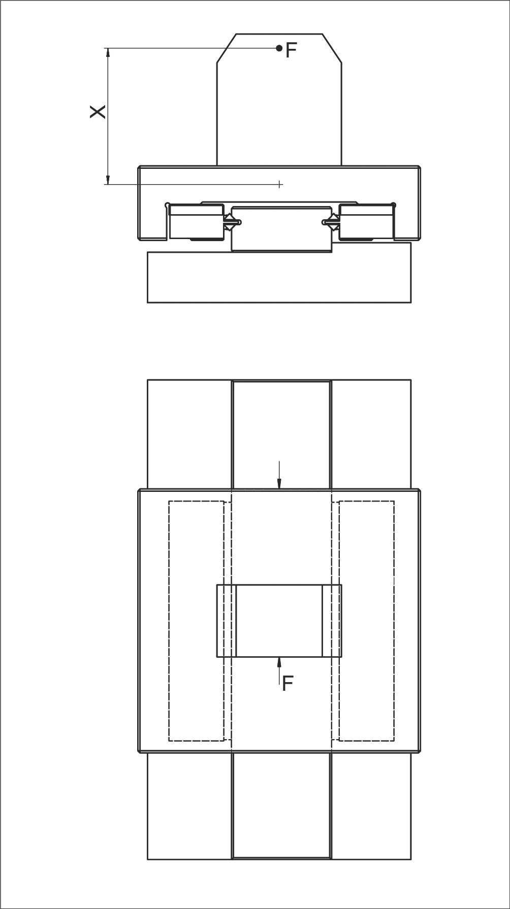
圖 12:循環單元力矩負載配置示意圖(顯示力 F 和力臂 X)
M 的計算 (Calculation for M)
力矩負載 M 低於允許負載 ML,因此此設計是正確的。
The moment load M is below the permissible load ML. Thus the design is correct.
符號說明 (Symbol Definitions)
| M | 縱向和橫向力矩負載 (Nm) | Moment load in Nm longitudinally and laterally |
| ML | 允許的縱向和橫向力矩負載 (Nm) | Permitted moment load in Nm longitudinally and laterally |
| X | 距離 (mm) | distance in mm |
| F | 負載 (N) | load in N |
範例 9:等效負載 PL 和 PQ
Example 9: Equivalent loads PL and PQ
假設條件 (Assumption):
- 循環單元型號 NRT 26 111(頂部)(Recirculating unit type NRT 26 111 (top))
- 循環單元型號 NRT 19 077(底部和側面)(Recirculating unit type NRT 19 077 (bottom and side))
給定值:
- C = 98'000 N(頂部循環單元)(top recirculating unit)
- C = 43'000 N(底部和側面循環單元)(bottom and side recirculating units)
- K = 700 mm
- K1 = 450 mm
- Rtmin = 0.5
- F = 83'000 N
- X = 500 mm
- Y = 100 mm
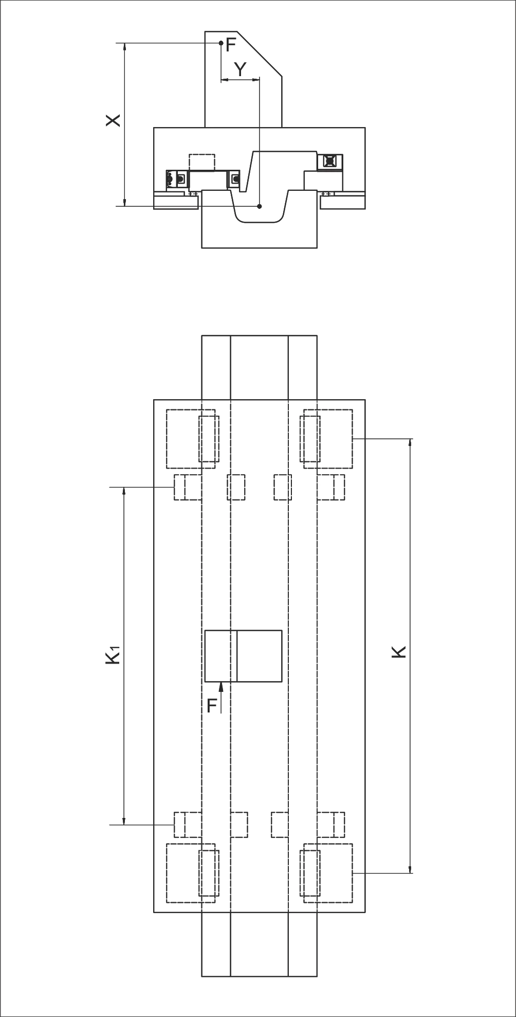
圖 13:NRT 26 111 和 NRT 19 077 循環單元配置示意圖
PL 與 PQ 的計算 (Calculation for PL and PQ)
縱向負載 (Load longitudinally)
橫向負載 (Load laterally)
| 符號 | 說明(單位) | English Description |
|---|---|---|
| P | 等效負載 (N) | Equivalent load in N |
| PL | 縱向等效負載 (N) | Equivalent load longitudinally in N |
| PQ | 橫向等效負載 (N) | Equivalent load laterally in N |
| F | 負載 (N) | load in N |
| X | 距離 (mm) | distance in mm |
| Y | 距離 (mm) | distance in mm |
| C | 每個循環單元的最大允許負載能力 (N) | Max. permissible load carrying capacity per recirculating unit in N |
| Rtmin | 修正因子 | Correction factor |
| K | 循環單元間距 (mm) | Spacing between the recirculating units in mm |
| K1 | 循環單元間距 (mm) | Spacing between the recirculating units in mm |