不同的应用领域需要直线导轨和循环单元的不同特性。
产品选择时需要考虑多种参数和因素。以下详细说明这些关键考量。
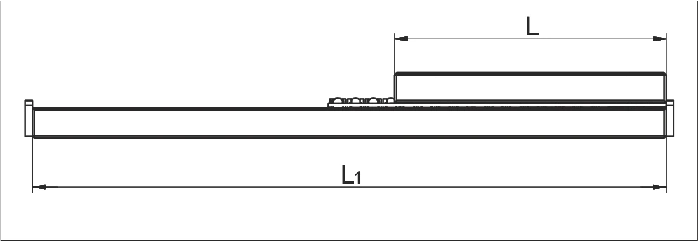
行程 H 与导轨长度 L 的关系
Relationship between stroke H and length of the guideway L
行程 < 400 mm
If the stroke is below 400 mm
行程 > 400 mm
If the stroke is above 400 mm
| L | = 直线导轨长度 (mm) Length of the linear guideway in mm |
| H | = 可能行程 (mm) Possible Stroke in mm |
计算滑块长度 K
Calculating the cage length K
对称行程
If the stroke is symmetrical
非对称行程
If the stroke is asymmetrical
H > H₁ + H₂
H₁₂ = H₁ + H₂
| K | = 滑块长度 (mm) Cage length in mm |
| L | = 直线导轨长度 (mm) Length of the linear guideway in mm |
| H | = 可能行程 (mm) Possible Stroke in mm |
| H₁ | = 大部分行程 = H/2 (mm) Large partial stroke in mm = H/2 |
| H₂ | = 小部分行程 = H/2 (mm) Small partial stroke in mm = H/2 |
| H₁₂ | = 有效部分行程 (mm) Effective partial stroke in mm |
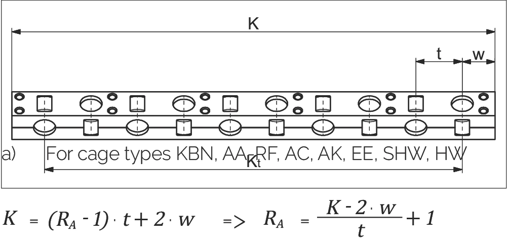
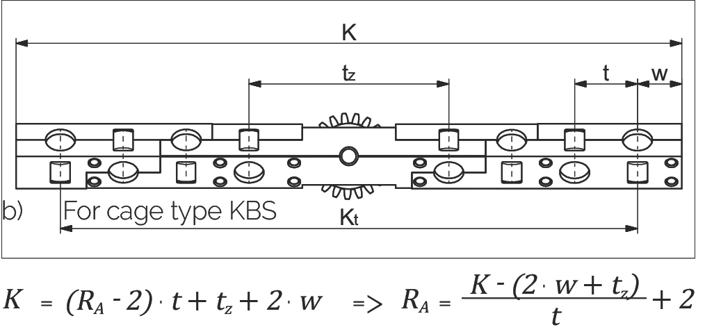
计算每个滑块的滚动元件数量 (RA)
Calculating the number of rolling elements (RA) per cage
a) 滑块类型:KBN, AA-RF, AC, AK, EE, SHW, HW
For cage types KBN, AA-RF, AC, AK, EE, SHW, HW
或
b) 滑块类型:KBS
For cage type KBS
或
| K | = 滑块长度 (mm) Cage length in mm | t | = 滑块分度 (mm) cage division in mm |
| RA | = 每个滑块的总可用滚动元件数 Total available rolling element per cage | Kt | = 负载长度 (mm) Load-bearing length in mm |
| w | = 从滑块起始到第一个滚动元件中心的距离 (mm) Distance from cage start to the middle of the first rolling element in mm | tz | = KBS 滑块中间段的长度 (mm) Length of the middle section for the KBS cage |
滑块长度 K 与平均导轨间距 Q 的关系
The relationship between the cage length K and the average guideway spacing Q
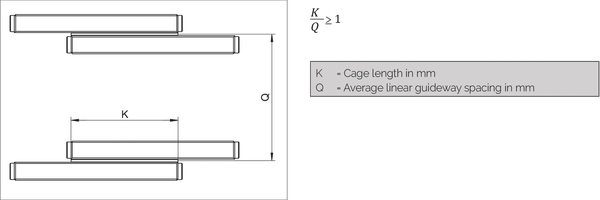
| K | = 滑块长度 (mm) Cage length in mm |
| Q | = 平均直线导轨间距 (mm) Average linear guideway spacing in mm |
超行程滑块的最大允许安装比例
The maximum permissible installation ratio in the case of overrunning cages
当需要在长导轨轨道上移动短工作台时,超行程滑块是一种有效的解决方案。在这种情况下, 导轨的短轨必须配备圆形导入部(特殊版本 EG,参见第 7.3 章),以使超行程滑块产生的脉动尽可能小。
最大允许安装比例 L : L₁
Maximum permitted installation ratios L to L₁:
| 固定式导轨 for fixed guideways | 1 : 2 |
| 叠置式导轨 for laid on guideways | 1 : 4 |
直线导轨的安装变体
Installation variants for linear guideways
直线导轨有四种安装变体。各种直线导轨也可以使用端盖形式的刮水器 (a₁)*。 在这四种情况下,会产生以下长度比率:
变体 1
- 等长轨道
- 对称/非对称行程
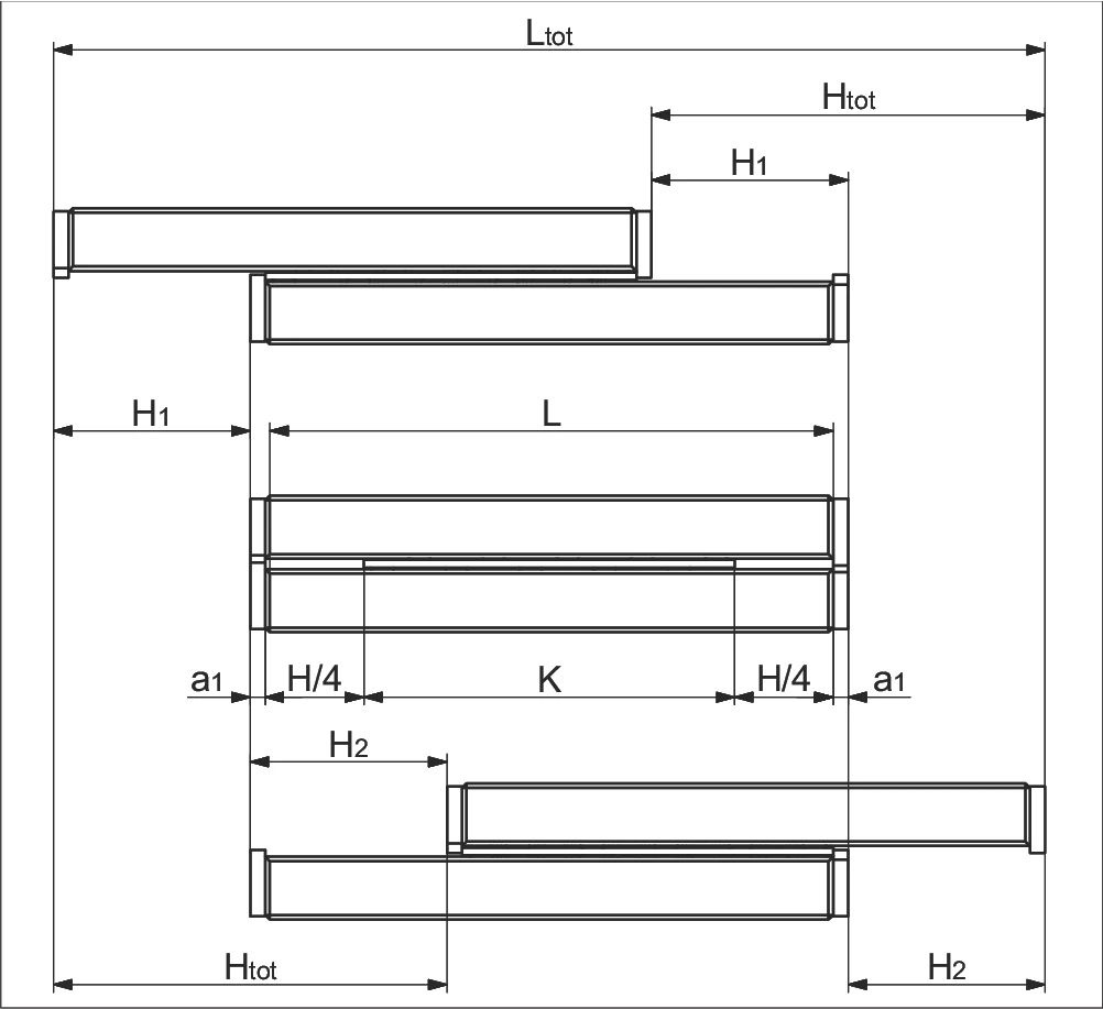
a) 无端螺钉、端盖和刮水器端盖
Without end screws, end pieces, and end pieces with wipers
b) 配备端螺钉、端盖和刮水器端盖**
For end screws, end pieces, and end pieces with wipers**
变体 2
- 等长轨道
- 单向行程
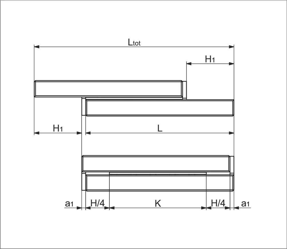
a) 无端螺钉、端盖和刮水器端盖
Without end screws, end pieces, and end pieces with wipers
b) 配备端螺钉、端盖和刮水器端盖**
For end screws, end pieces, and end pieces with wipers**
变体 3
- 不等长轨道
- 对称/非对称行程
- 短轨附加
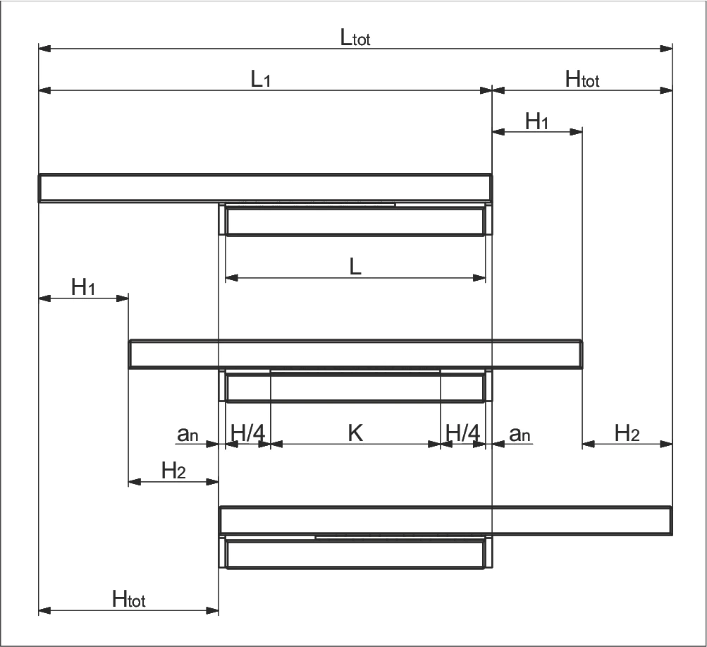
a) 无端螺钉、端盖和刮水器端盖
Without end screws, end pieces, and end pieces with wipers
b) 配备端螺钉、端盖和刮水器端盖**
For end screws, end pieces, and end pieces with wipers**
变体 4
- 不等长轨道
- 对称/非对称行程
- 长轨附加
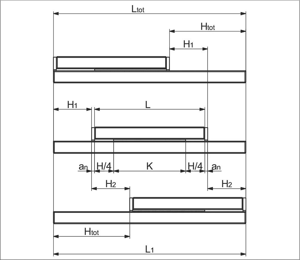
a) 无端螺钉、端盖和刮水器端盖
Without end screws, end pieces, and end pieces with wipers
b) 配备端螺钉、端盖和刮水器端盖**
For end screws, end pieces, and end pieces with wipers**
参数说明
| K | = 滑块长度 (mm) Cage length in mm | H | = 可能行程 (mm) Possible stroke in mm |
| H₁ | = 大部分行程 = H/2 (mm) Large partial stroke in mm = H/2 | H₂ | = 小部分行程 ≤ H/2 (mm) Small partial stroke in mm ≤ H/2 |
| Htot | = 有效部分行程 (mm) Effective partial stroke in mm | H12 | = 总部分行程 = H1 + H2 (mm) Total partial stroke in mm = H1 + H2 |
| L | = 导轨长度 (mm) Length in mm | L₁ | = 长轨长度 (mm) Length in mm |
| Ltot | = 总长度 (mm) Total length in mm | an | = 端盖厚度 (mm) Thickness of the end piece in mm |
* a₁ 端螺钉、端盖和刮水器端盖,见第 5 章
** 刮水器可能会影响直线导轨的运行特性