The varied areas of application require different characteristics of linear guideways and recirculating units.
Various parameters and considerations are critical for product selection. These are described in detail below.
Cage Length K ⇄ Number of Rolling Elements R_A
Bi-directional conversion between K and R_A
Stroke H / Guideway Length L Ratio Checker
Stroke / Guideway Length Ratio Checker
Relationship between stroke H and length of the guideway L
Relationship between stroke H and length of the guideway L
If the stroke is below 400 mm
If the stroke is below 400 mm
If the stroke is above 400 mm
If the stroke is above 400 mm
| L | Length of the linear guideway in mm Guideway length parameter |
|---|---|
| H | Possible Stroke in mm Stroke parameter |
Calculating the cage length K
Calculating the cage length K
If the stroke is symmetrical
If the stroke is symmetrical
If the stroke is asymmetrical
If the stroke is asymmetrical
H > H₁ + H₂
H₁₂ = H₁ + H₂
| K | Cage length in mm Cage length |
|---|---|
| L | Length of the linear guideway in mm Guideway length |
| H | Possible Stroke in mm Possible stroke |
| H₁ | Large partial stroke in mm = H/2 Large partial stroke |
| H₂ | Small partial stroke in mm = H/2 Small partial stroke |
| H₁₂ | Effective partial stroke in mm Effective partial stroke |
Calculating the number of rolling elements (R_A) per cage
Calculating the number of rolling elements (R_A) per cage
a) For cage types: KBN, AA-RF, AC, AK, EE, SHW, HW
For cage types KBN, AA-RF, AC, AK, EE, SHW, HW
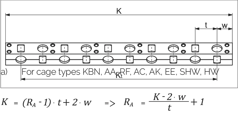
or
b) For cage type: KBS
For cage type KBS
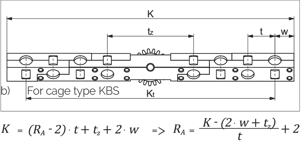
or
| K | Cage length in mm Cage length |
|---|---|
| t | Cage division in mm Cage division |
| RA | Total available rolling element per cage Total rolling elements per cage |
| Kt | Load-bearing length in mm Load-bearing length |
| w | Distance from cage start to the middle of the first rolling element in mm Distance to first rolling element |
| tz | Length of the middle section for the KBS cage Middle section length (KBS) |
The relationship between the cage length K and the average guideway spacing Q
The relationship between the cage length K and the average guideway spacing Q
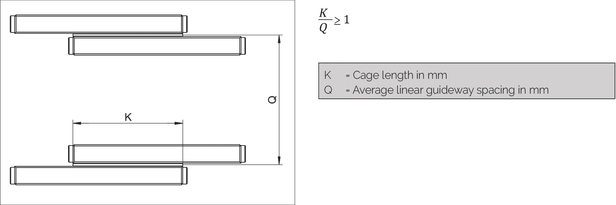
| K | Cage length in mm Cage length |
|---|---|
| Q | Average linear guideway spacing in mm Average guideway spacing |
The maximum permissible installation ratio in the case of overrunning cages
The maximum permissible installation ratio in the case of overrunning cages
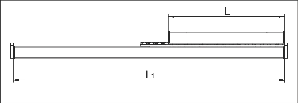
Overrunning cages are expedient if a short table is to be moved on a long guideway track. In each case the short rail for the guideway must have a rounded run-in (special version EG, see chapter 7.3) so that the overrunning cage causes as little pulsation as possible.
Maximum permitted installation ratios L : L₁
Maximum permitted installation ratios L to L₁:
| for fixed guideways Fixed guideway installation | 1 : 2 |
| for laid on guideways Laid-on guideway installation | 1 : 4 |
Installation variants for linear guideways
Installation variants for linear guideways
There are four installation variants for linear guideways. The various linear guideways can be also used with wipers in the form of end pieces (a₁)*. In these four cases, the following length ratios result:
Variant 1
- Equal length rails
- Symmetric / asymmetric stroke
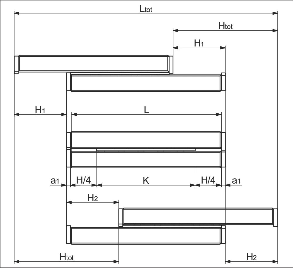
a) Without end screws, end pieces, and end pieces with wipers
Without end screws, end pieces, and end pieces with wipers
b) For end screws, end pieces, and end pieces with wipers**
For end screws, end pieces, and end pieces with wipers**
Variant 2
- Equal length rails
- Unidirectional stroke
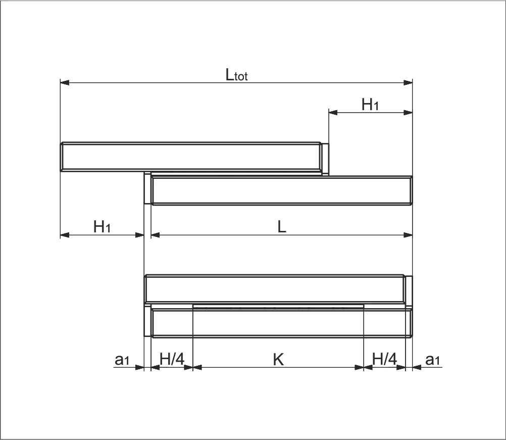
a) Without end screws, end pieces, and end pieces with wipers
Without end screws, end pieces, and end pieces with wipers
b) For end screws, end pieces, and end pieces with wipers**
For end screws, end pieces, and end pieces with wipers**
Variant 3
- Unequal length rails
- Symmetric / asymmetric stroke
- Short rails attached
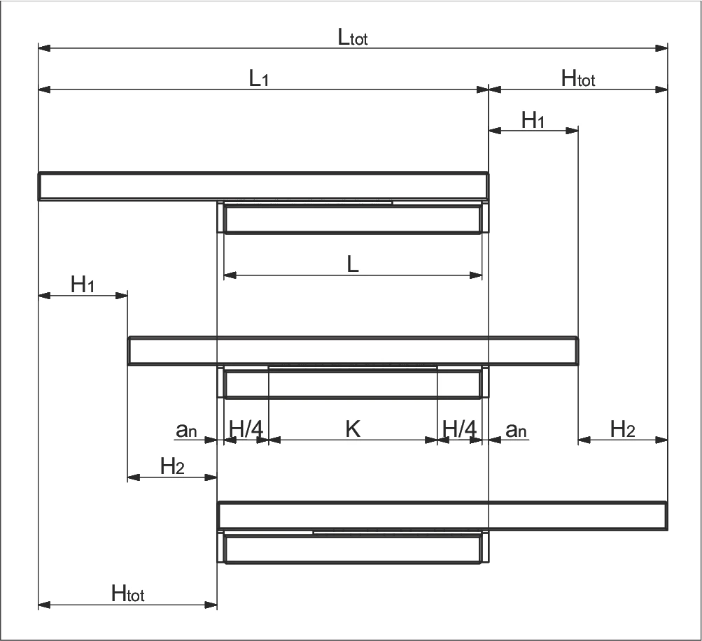
a) Without end screws, end pieces, and end pieces with wipers
Without end screws, end pieces, and end pieces with wipers
b) For end screws, end pieces, and end pieces with wipers**
For end screws, end pieces, and end pieces with wipers**
Variant 4
- Unequal length rails
- Symmetric / asymmetric stroke
- Long rails attached
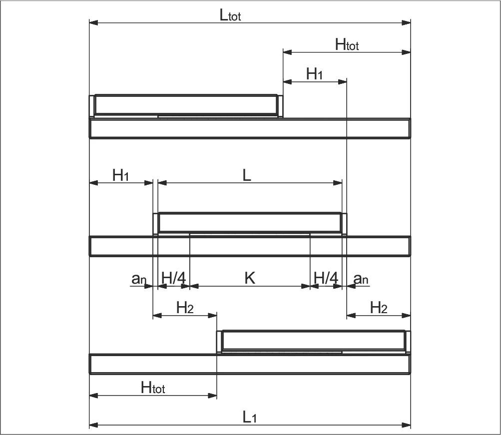
a) Without end screws, end pieces, and end pieces with wipers
Without end screws, end pieces, and end pieces with wipers
b) For end screws, end pieces, and end pieces with wipers**
For end screws, end pieces, and end pieces with wipers**
Parameters
| K | Cage length in mm Cage length |
|---|---|
| H | Possible stroke in mm Possible stroke |
| H₁ | Large partial stroke in mm = H/2 Large partial stroke |
| H₂ | Small partial stroke in mm ≤ H/2 Small partial stroke |
| tot | Effective partial stroke in mm Effective partial stroke |
| L | Length in mm Guideway length |
| L₁ | Length in mm Long-rail length |
| Ltot | Total length in mm Total length |
| an | Thickness of the end piece in mm End piece thickness |
* a₁ end screws, end pieces, and end pieces with wipers, see chapter 5
** Wipers can influence the run characteristics of the linear guideways