Clearance Fit
If the rotating ring is not supported by an interference fit, radial displacement of the rotating shaft to the stator center is possible. The clearance from the fit to the bearing bore (or from the fit to the bearing outside diameter) applies to the radial runout of the rotating outer ring (or rotating inner ring).
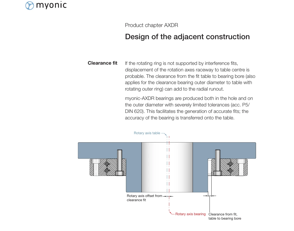
myonic AXDR bearings are less sensitive to non-positively locked shafts than AXRY bearings due to their solid rings. However, a reduction in shaft rigidity and possible radial runout problems, or displacement of the rotating shaft on overload, must be accepted.
Radial Runout Measurement Note
A radial runout measurement performed with a centering tabletop and a mounted measuring ball does not accord with the catalog values. During such a precisely centered measurement, only the radial runout of the raceway and the form errors of the measuring construction are recorded. The myonic radial runout values include the radial runout error of the raceway and the roundness of the bore.
Centered Shafts / Tables
Execution via a shaft clearance fit with centering of the rotating shaft is possible. Due to their solid rings, AXDR bearings are less sensitive to non-positively locked shafts than AXRY bearings. However, a reduction in shaft rigidity and possible radial runout problems, or displacement of the rotating shaft on overload, must be accepted.
Recommended Connection Dimensions
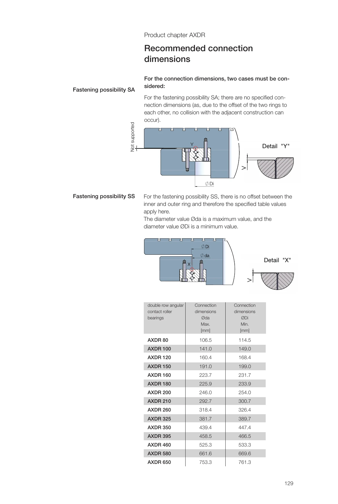
Two cases must be considered for the connection dimensions:
Fastening Method SA
For fastening method SA, there are no specified connection dimensions because the offsets of the two rings cancel each other out. No collision with the adjacent construction occurs.
Fastening Method SS
For fastening method SS, there is no offset between the inner and outer rings, so the specified table values apply. The diameter value ODa is a maximum, and the diameter value IDi is a minimum.
| Double Row Angular Contact Roller Bearing | Connection Dimension Ø da [mm] | Connection Dimension Ø Di [mm] |
|---|---|---|
| AXDR 80 | 106.5 | 114.5 |
| AXDR 100 | 141.0 | 149.0 |
| AXDR 120 | 160.4 | 168.4 |
| AXDR 150 | 191.0 | 199.0 |
| AXDR 160 | 223.7 | 231.7 |
| AXDR 180 | 225.9 | 233.9 |
| AXDR 200 | 246.0 | 254.0 |
| AXDR 210 | 292.7 | 300.7 |
| AXDR 260 | 318.4 | 326.4 |
| AXDR 325 | 381.7 | 389.7 |
| AXDR 350 | 439.4 | 447.4 |
| AXDR 395 | 458.5 | 466.5 |
| AXDR 460 | 525.3 | 533.3 |
| AXDR 580 | 661.6 | 669.6 |
| AXDR 650 | 753.3 | 761.3 |
Positioning Hole
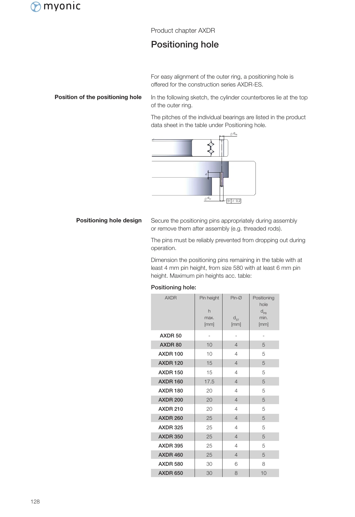
For easy alignment of the outer ring, a positioning hole is offered for the construction series AXDR-ES.
In the following sketch, the cylindrical counterbore lies at the top of the outer ring. The pitches of the individual bearings are listed in the product data sheet under "Positioning hole".
Positioning Hole Design
Secure the positioning pins appropriately during assembly, or remove them after assembly (e.g., threaded rods).
The pins must be reliably prevented from dropping out during operation.
Dimension the positioning pins remaining in the table with at least 4 mm pin height, and from size 580 with at least 6 mm pin height.
Positioning Hole Dimensions
| AXDR | Pin Height h max. [mm] | Pin Ø dst [mm] | Positioning Hole Ø dbo min. [mm] |
|---|---|---|---|
| AXDR 50 | - | - | - |
| AXDR 80 | 10 | 4 | 5 |
| AXDR 100 | 10 | 4 | 5 |
| AXDR 120 | 15 | 4 | 5 |
| AXDR 150 | 15 | 4 | 5 |
| AXDR 160 | 17.5 | 4 | 5 |
| AXDR 180 | 20 | 4 | 5 |
| AXDR 200 | 20 | 4 | 5 |
| AXDR 210 | 20 | 4 | 5 |
| AXDR 260 | 25 | 4 | 5 |
| AXDR 325 | 25 | 4 | 5 |
| AXDR 350 | 25 | 4 | 5 |
| AXDR 395 | 25 | 4 | 5 |
| AXDR 460 | 25 | 4 | 5 |
| AXDR 580 | 30 | 6 | 8 |
| AXDR 650 | 30 | 8 | 10 |