SCHNEEBERGER MONORAIL offers a variety of clamping and braking components for fixing or braking guideway systems. These components play a critical role in machine tools, automation equipment, and applications requiring precise positioning.
4.16.1 Construction and Application Areas
Construction principles, activation methods, and typical application scenarios for clamping and braking components.
Basic Construction
Clamping and braking components are built in a similar way to the carriages in SCHNEEBERGER MONORAIL guideways. They consist of a body, which is screwed on to the machine table and surrounds the guide rail profile. Instead of the rolling elements, radial moving clamping jaws are positioned on both sides of the guide rail, which upon activation rest against the guide rail in the cavity between the tracks and clamp or brake the axis. Individual types for guide rails with AM measuring system use the guide rail collar as a contact surface.
In their disengaged state, there is no contact between guide rail and clamping components; the clamping components do not therefore perform any guiding function.
There are narrow and wide types; the main dimensions of the components are mainly based upon DIN 645 and thus correspond with carriage cross sections.
The activation of the clamping pads occurs either by synchronously switched two-sided plunging components or by one individual plunging component with a floating bearing. In each case it guarantees that the clamping motion exerts minimal or no transverse forces on the connecting structure.
Structural Types
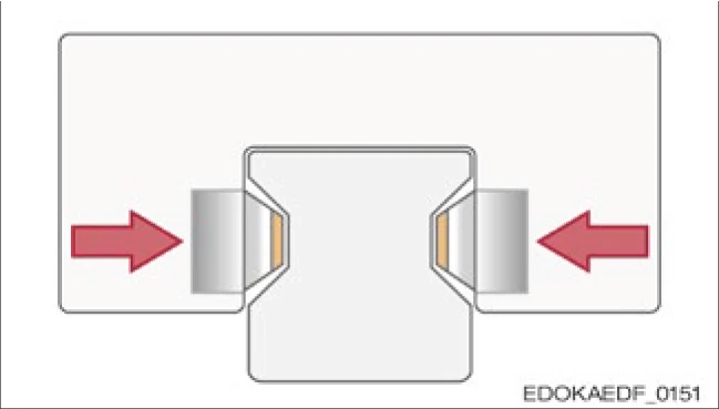
Contact area between the raceways. Not suitable for guide rails equipped with AMS!
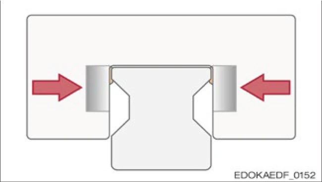
Contact area with guide rail flange. Suitable for guide rails equipped with AMS!
Application Areas
SCHNEEBERGER supplies clamping and braking components for MR and BM MONORAIL guideways. Typical areas of use are:
- Fixing the position of linear axes in order to unload the drive
- Clamping machine tables to absorb axial forces during machining
- Fixing vertical axes at standstill
- Transport locking of axes
- Braking and holding linear motor axes in the event of a power failure
4.16.2 Clamping and Braking Component Types
There are various types of stabilizing elements, which differ in function, pressure generation method, and effect.
Functional Classification
Based on function, they can be distinguished as clamping elements and braking elements. Clamping elements are used to fix idling machine axes. Braking elements are able to brake axes from motion. For this purpose, they are equipped with special slideway coatings designed so that the guide rail is not damaged.

Caution
Component damage due to braking system failure
- Braking components are designed for emergency stop situations and must not be used as operational brakes!
Pressure Medium
Distinction based on pressure generation method:
Manual
Clamping force generated through manual operation, suitable for low-frequency operation applications.
Pneumatic
Uses compressed air to generate clamping force, fast response, suitable for automation applications.
Hydraulic
Uses hydraulic oil to generate high clamping force, suitable for heavy-load applications.
Electric
Motor-driven, precise control of clamping force, suitable for applications requiring high precision.
Effect Classification
There are both active elements, i.e., elements that act by applying pressure, and passive elements, in which case their holding force is achieved through pressure drop. For these elements, the holding force is generated by an integrated spring energy storage. The pressure medium is used to release the holding force, or can be used in combination with the spring energy storage in elements with so-called positive connection to increase their holding force.
4.16.3 Type Overview
The following tables provide an overview of different types, their characteristics, and uses:
Pneumatic Clamping and Braking Component Series

Product Series Overview: HK, MK, MKS, MBPS, BWPS, TKPS, UBPS, LBPS
| Characteristic/Series | HK | MK | MKS | MBPS | BWPS | TKPS | UBPS | LBPS |
|---|---|---|---|---|---|---|---|---|
| Pressure Medium | ||||||||
| Manual | ● | |||||||
| Pneumatic | ● | ● | ● | ● | ● | ● | ● | |
| Hydraulic | ||||||||
| Electric | ||||||||
| Spring Energy Storage | ● | ● | ● | ● | ● | ● | ||
| PLUS Connection | ● | ● | ● | ● | ||||
| Braking Element | ● | ● | ● | ● | ● | |||
| DIN 645 Compatible | ● | ● | ● | |||||
| Guide Rail Type | ||||||||
| MR Roller | ● | ● | ● | ● | ● | ● | ● | ● |
| MR with AMS | ● | ● | ● | |||||
| BM Ball | ● | ● | ● | |||||
Note: ● = Applicable
Order code: Series xx, where xx = size (e.g., "MKS xx")
Hydraulic and Electric Clamping Component Series

Product Series Overview: KWH, KBH, KBHS, MKE
| Characteristic/Series | KWH | KBH | KBHS | MKE |
|---|---|---|---|---|
| Pressure Medium | ||||
| Manual | ||||
| Pneumatic | ||||
| Hydraulic | ● | ● | ● | |
| Electric | ● | |||
| Spring Energy Storage | ● | |||
| PLUS Connection | ||||
| Braking Element | ● | ● | ||
| DIN 645 Compatible | ● | ● | ||
| Guide Rail Type | ||||
| MR Roller | ● | ● | ● | ● |
| MR with AMS | ||||
| BM Ball | ● | |||
Note: ● = Applicable
Order code: Series xx, where xx = size (e.g., "MKS xx")