9.1 Visual Inspection Check List
During guideway maintenance, it is essential to ensure the following conditions are not damaged and can prevent damage to them through visual inspection:
- Check the guideway surface for damage.
- Check the wiper, see page 57 "Checking the results of the installation".
- Check cross wiper for damage/wear.
- Check additional wipers (if installed) for damage/wear.
- Check whether the carriage has sufficient lubrication (whether lubricant is discharged from the carriage).
- Remove the carriage and check for dust (see "Handling the carriage" on page 20).
- Remove the carriage and check for damage to plastic parts (see "Handling the carriage" on page 20).
- Remove residual chips from the vicinity of the guideway.
9.2 Cleaning
ATTENTION!
Risk of material damage due to improper cleaning!
May cause damage to plastics and guideways.
- All parts should only be wiped with cleaning agent, using cleaning alcohol or white spirit. Do not use any cleaning agents or solvents that could damage plastics.
- Clean the guideway with a soft, lint-free cloth. Do not use compressed air.
- Avoid direct contact of tools with the guideway magnetic measuring tape.
9.3 Replacing Defective Components
ATTENTION!
Risk of material damage posed by bending sensor slide springs!
When transferring carriages with housing for the AMS measuring system with built-in read head to/from guideway, sensor slide springs can become bent.
- Dismount the read head before transferring carriage to/from guideway.
ATTENTION!
Risk of material damage posed by scratching the measuring scale!
Swarf caught beneath metal wipers can scratch the magnetic measuring scale.
- Only use metal wipers designated for the AMS measuring system on guideways with magnetic measuring scale.
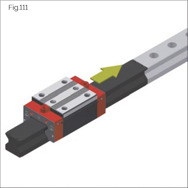
Fig.111
- The carriage and guide rail form a single unit. In the case of matched designs, ensure that the carriages of different guide rails are not interchanged.
- To prevent rolling elements from being dislodged from carriages, use an MRM/MBM assembly rail when transferring carriages to and from guide rail. The MRM/MBM assembly rail is not included in the standard delivery.
- Should one carriage become damaged, replace all carriages. Should it be unknown which accuracy levels are installed, a G0 system can be installed. This ensures that the original accuracy levels are achieved.
Carriage Replacement Procedure
Identifying the carriage for ordering spare parts:
- The relevant carriage can be identified by its label, see 3.3 Labelling of guide rails and carriages on page 9.
Spare Parts
- STP front plate
- QAS cross wiper for MONORAIL MR/BM
- FRB front panel for MONORAIL MR
- ZCV additional wiper for MONORAIL MR and ZBV for MONORAIL BM
- ASM metal wiper for MONORAIL MR and ABM for MONORAIL BM
- SPL lubrication plate
- Screws
Guide Rail Replacement Procedure
Identifying the guide rail for ordering spare parts:
- The relevant guide rail can be identified by its label, see 3.3 Labelling of guide rails and carriages on page 9.
Spare Parts
- Screw covers
- Screws
- Transfer carriages onto MRM/MBM assembly rails.
- Leave carriages on assembly rails during transportation or storage. Ensure that carriages and associated guide rails are not interchanged.
- Individually transfer carriages back onto their associated guide rail from assembly rails.
9.4 Replacing the Read Head
CAUTION!
Risk of crushing due to moving axis!
May cause personal injury.
- Before replacing the read head, switch off the main switch and ensure it cannot be switched on again. If necessary, secure the axis.
ATTENTION!
Risk of material damage due to short-circuit current!
The electronics in the read head can be damaged by short-circuit current.
- Before replacing the read head, disconnect the power supply and ensure it cannot be restored without authorization.
Removing the Read Head
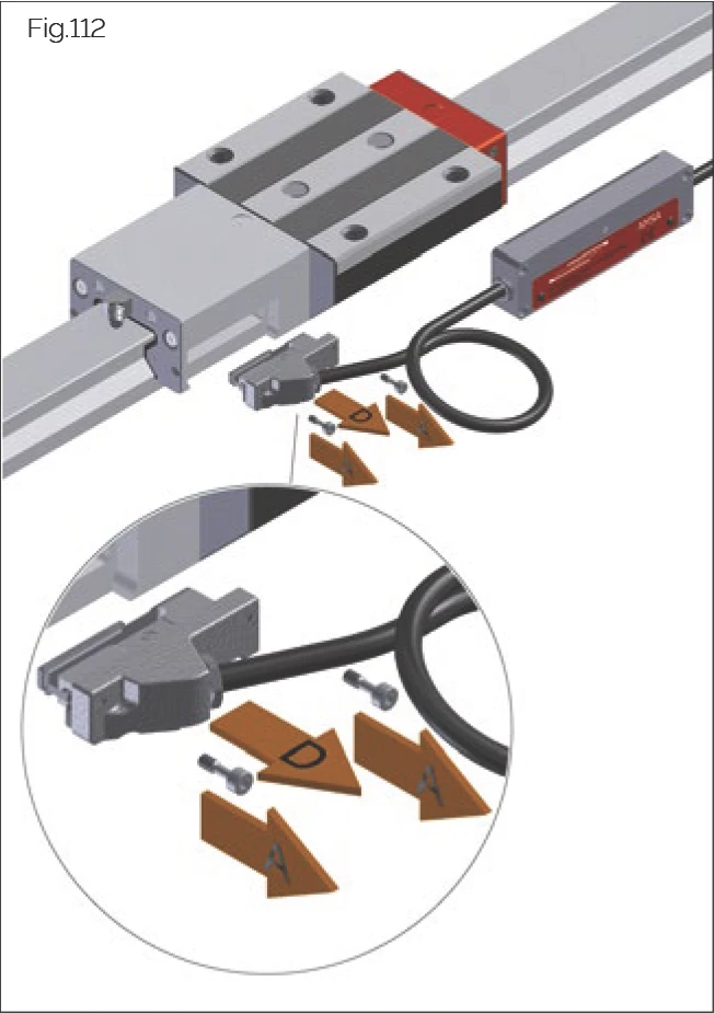
Fig.112
- Switch off the main switch and ensure it cannot be switched on again.
- If necessary, remove the protective cover.
- Ensure proper handling of the decommissioned axis.
- Disconnect the read head connecting cable.
- Disconnect the sensor cable from the electronics housing (if applicable).
- Loosen the fastening screws securing the read head to the housing.
- Remove the cover plate screws for AMSABS 4B.
- For AMSABS 3B, slide the installed read head sideways out of the guideway until it is completely free to rotate, moving it away from the mounting surface at the correct angle.
- Carefully remove the read head from the mounting surface at the correct angle.
- Document the fault and serial number and package the read head.
Installing the Read Head
- Check the read head mounting surface on the housing for contaminants.
- Clean the magnetic measuring scale.
- Carefully unpack the new read head.
- If necessary, clean the sensor slider of the read head.
- For AMSABS, activate the battery (see "9.5 Battery AMSABS / AMSABS 3L").
- Carefully insert the read head into the recess in the housing at a right angle to the mounting surface, ensuring that it lies flat.
- For AMSABS 3B and 4B, slide the read head parallel to the guideway until it locks into place:
- The measuring system automatically identifies the absolute position during installation.
- The system is ready for operation immediately after installation.
- The LED lights up green once the controller is powered on.
- Tighten the fastening screws on the housing (tightening torque 1.1 Nm).
- Route the cables and secure the separate electronics housing (see "Routing electronics housing and cables", page 54).
- Insert the connecting cable plug and hand-tighten the union nut.
- Switch the power supply back on.
- For AMS with operating status display, ensure that the LED lights up green.
- Check the machine zero point and recalibrate if necessary: perform a reference run on the drive controller.
ATTENTION!
Risk of material damage due to collision!
Failure to check and adjust (if necessary) the machine zero point may cause machine components to collide with other components.
- Calibrate the zero point after every read head installation.
Note: Position identification between equivalent reference marks may vary by ± 0.5 mm depending on the read head.
9.5 Battery AMSABS / AMSABS 3L
Battery: Lithium Type AA- LS 14500- 3.6V 2450 mAh- SAFT
Battery Status Display
For AMSABS, low battery status is indicated by the operating status LED and, if necessary, by the machine controller.
Operation
The electronics housing (sensor unit) contains an accumulator and a buffer battery that ensure system functionality even when the machine is switched off. Short machine shutdowns (up to 4 weeks) are covered by the accumulator and do not affect the service life of the battery. In the typical use case where the machine operates regularly, the buffer battery therefore guarantees proper functioning of the sensor unit for many years. For such cases, SCHNEEBERGER recommends replacing the battery proactively every 5 years.
If the external power system is switched off for an extended period, the position measurement of the system is maintained for approximately 1.5 years, although regular movement of the read head shortens this period. If the machine or measuring system is shut down, it is recommended to reinsert the activation strip and the magnet beneath it into the electronics housing (see page 17 "Preparing the measuring system installation") in order to disconnect the power supply to the sensor unit and prevent the battery from being depleted; the absolute position must then be reset when the system is put back into service.
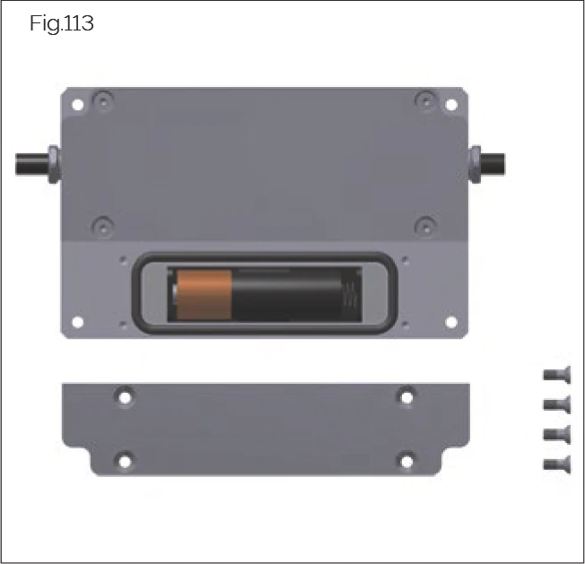
Fig.113
- Loosen the battery compartment on the back of the electronics housing.
- Remove the old battery.
- Insert the new battery, ensuring correct orientation.
- Check that the O-ring is correctly installed in the groove and ensure the O-ring, groove, and support surface are clean.
- Refit the battery compartment cover and secure it with screws (tightening torque 0.3 Nm).
- Dispose of old batteries properly according to applicable national regulations.
Only use batteries with a manufacturing date no more than one year old. Before replacement, check the manufacturing date marked on the battery.
| Country | China | UK | France |
|---|---|---|---|
| Format | Year Month Day | Year Day | Year Day Traceability code |
| Example | 16 02 23A | 16 054 | 16 054 A023 |
| Meaning | Battery manufactured on 23 February 2016; A or blank is an internal control code | Battery manufactured on day 54 of 2016 (23 February) | Battery manufactured on day 54 of 2016 (23 February); internal batch code A023 |
9.6 Checking and Replacing Accessories and Wear Parts
9.6.1 End Plates and Additional Wipers
Ensuring proper carriage function is a prerequisite for ensuring the guideway provides contamination-free lubrication and prevents contaminants from entering. Generally, seals are designed to be maintenance-free. They should be regularly checked for damage and wear at specified intervals.
Seals on end plates and additional wipers should be regularly checked for damage, at least every 6 months, and replaced if necessary.
Replacing Cross Wipers and Additional Wipers
DANGER!
Risk of death due to loss of rolling elements!
For MONORAIL BM, the end plate is part of the rolling element recirculation unit. Removing the end plate will cause loss of rolling elements. Possible consequences include death and serious injury.
- For MONORAIL BM, the end plate of the carriage must not be removed under any circumstances.
When replacing cross wipers and additional wipers, remove the fastening screws from the end plate.
The following must be observed when performing this operation:
- For MONORAIL BM, the end plate must not be removed under any circumstances.
- For MONORAIL MR, the end plate does not need to be removed to replace the cross wiper.
- Always use an assembly guideway to transfer carriages to and from the guideway.
- For carriages with measuring systems, always remove the read head from the housing before transferring carriages to and from the guideway.
Cross Wipers
Checking Cross Wipers
Regularly check cross wipers for wear and replace if necessary.
Replacing Cross Wipers in the Case of MONORAIL MR
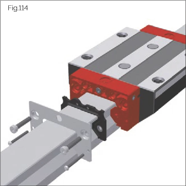
Fig.114
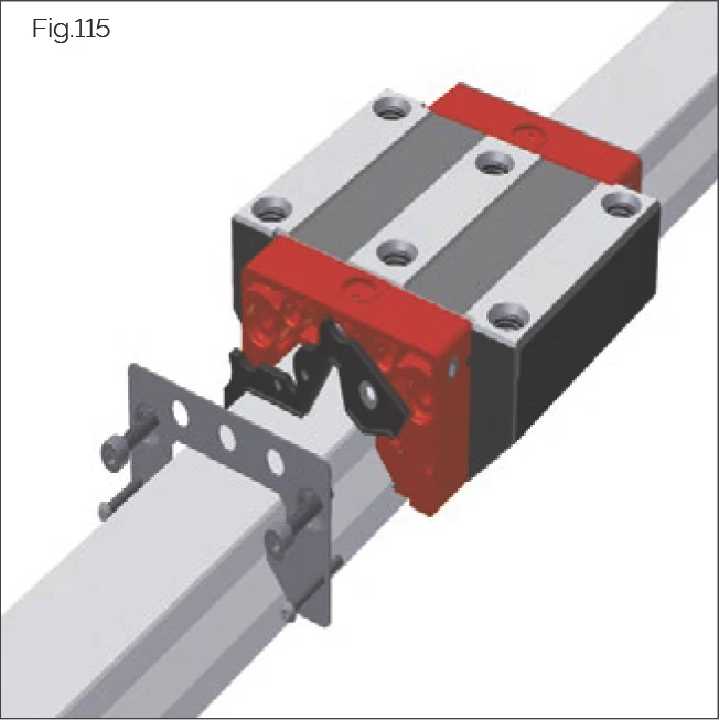
Fig.115
- Leave carriages on the guideway.
- Remove the upper and lower screws.
- Remove front panel and accessories (where applicable) from the front plate (can be left on the guideway).
- Disengage the cross wiper from the front plate and, to remove it, pull over the guide rail while holding the front plate in place.
- Pull the new cross wiper onto the guide rail and press it into the front plate (taking care with the rotation lock).
- Slide accessories and front panel back onto the front plate.
- Tighten the screws. See 12.2 Screw tightening torques on page 74.
Replacing Cross Wipers in the Case of MONORAIL BM Front Plates
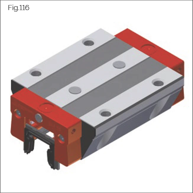
Fig.116
In the case of MONORAIL BM, only the cross wipers in the front plate should be replaced.
The screws of the front plate must not be loosened during this process.
- Use an assembly rail to transfer the carriage from the guideway.
- Pull the defective cross wiper downward and out of the front plate housing.
- Fully slide the cross wiper into the guideway groove of the front plate.
→ The cross wiper will snap in audibly.
- Remount the carriage onto the guide rail.
ZCV/ZBV Additional Wipers
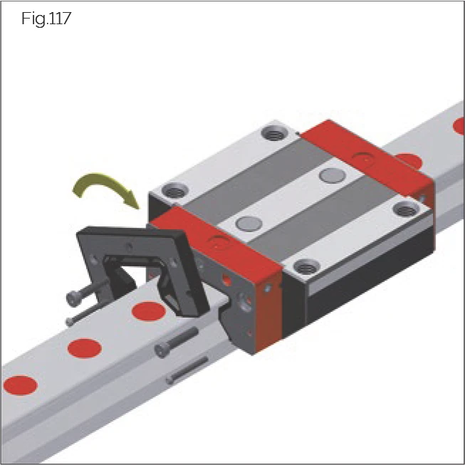
Fig.117
Their flexibility allows additional wipers to be replaced directly on the guideway. They can also be installed or removed from carriage end plates that cannot be removed from the guideway.
Note: Lubrication fittings on the end plate are sealed with stop screws. During installation of ZCV/ZBV additional wipers, these stop screws are covered. When screwing lubrication nipples into additional wipers, the stop screws underneath must be removed.
- Loosen the screws on the carriage end plate.
- Move the additional wiper a few millimeters away from the end plate while holding the end plate.
- Pull the wiper off the guideway and replace 4 metal surfaces (if necessary).
- Pull the new additional wiper over the guideway cross-section (or track end).
- Press the wiper onto the end plate, aligning on its surface through the centering pin.
- Ensure the wiper is evenly positioned and tighten the screws. For maximum tightening torque, see page 74 "Screw tightening torques".
Longitudinal Seals
Longitudinal seals are firmly connected to the carriage or housing.
Checking Longitudinal Seals
To identify damage to longitudinal seals, completely remove the carriage and perform a visual inspection of the sealing lip.
Replacing Longitudinal Seals
For longitudinal seals firmly connected to the carriage or housing that are damaged, the entire carriage must be replaced.
Metal Wipers
Checking ASM/ABM Metal Wipers
- Check the end plate for mechanical damage and whether the gap with the guideway profile is evenly positioned.
- Replace or readjust the metal wiper based on the results.
Replacing ASM/ABM Metal Wipers
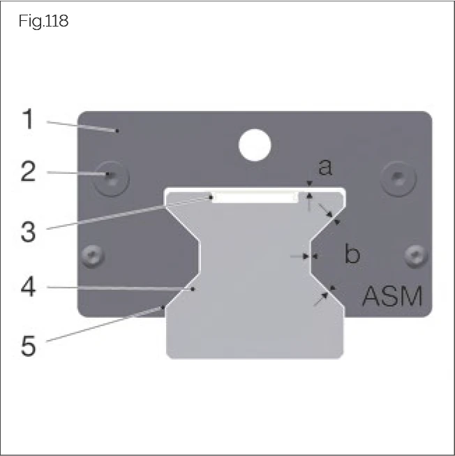
Fig.118
- Loosen the screws on the front plate.
- Pull the metal wiper off the end of the guide rail.
- Slide the new metal wiper on from the end of the guide rail.
- Tighten the fastening screws until the wiper can no longer be moved by hand.
- Using a feeler gauge and referring to the relevant documentation, ensure that the gap between the guide rail and the edges of the wiper is even.
- Hold the metal wiper in place and tighten the fastening screws; for tightening torques see "Screw tightening torques" (page 75).
- Check the gap again after tightening the screws.
- When the carriage is mounted on a guide rail already fitted with a MAC cover strip, ensure that the gap is maintained.
Gap Dimensions
- a = 0.9 mm ± 0.05 mm
- b = 0.25 mm ± 0.05 mm
When using AMS guide rails, ASM-A metal wipers must be used. This type is shortened by 2 mm on both sides at the base of the prism (dimension b). This metal wiper can be identified by the marking on its front face.
9.6.2 Rail Covers
Rail covers include plugs, cover strips, and bellows. These are prerequisites for ensuring the proper functioning of the carriage seal system and one of the factors responsible for ensuring that the guideway provides an extended service life. Rail covers should be checked at regular intervals (at least every 6 months) for damage and wear, and replaced where necessary.
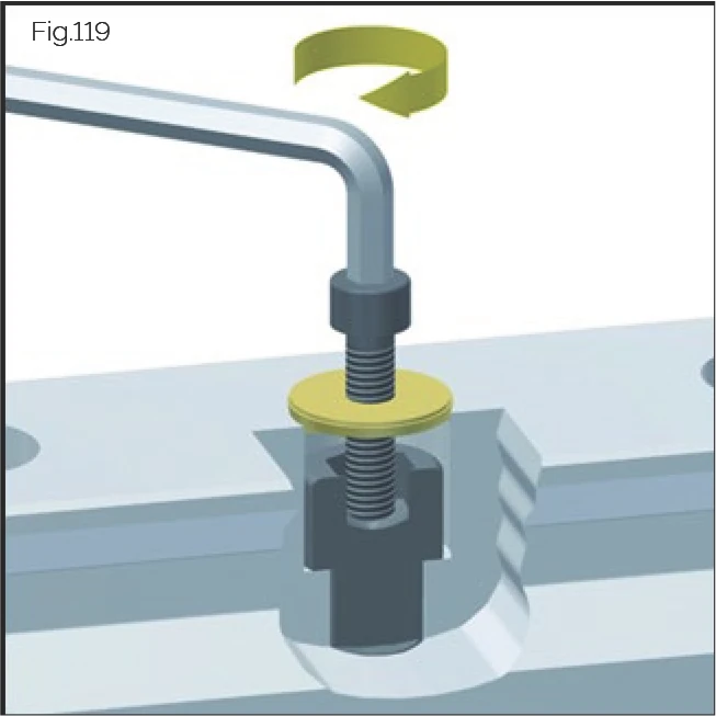
Fig.119
Plugs
Plugs must be fitted flush with and parallel to the guide rail surface. Protruding or scratched plugs may cause damage to carriage wipers. Where plugs sit too deeply, this may lead to the build-up of dirt in the guide rail fixing holes or to damage to carriage wipers caused by the sharp edges of these holes.
Checking Plugs
Check plugs for dirt and swarf in the fixing holes or on the guide rail surface. Dirt and swarf that are not wiped away as the carriage passes over the guide are indicative of improperly functioning plugs. Plugs should be replaced in this case and carriage wipers checked.
MAC/BAC Cover Strips
Checking MAC/BAC Cover Strips
Replace cover strips in the following cases:
- Cover strip is bent or scratched
- Cover strip has longitudinal offset
- Cover strip groove has loose ends
- Cover strip is loose
Replacing MAC/BAC Cover Strips
For cover strip replacement, see page 44 "MAC/BAC cover strips".
FBM/FBB Bellows
Checking Bellows
Check bellows for damage such as tears or holes. Check whether bellows slide smoothly over the guideway. If damaged, bellows must be replaced; if applicable, also check the MONORAIL guideway for damage or contamination.
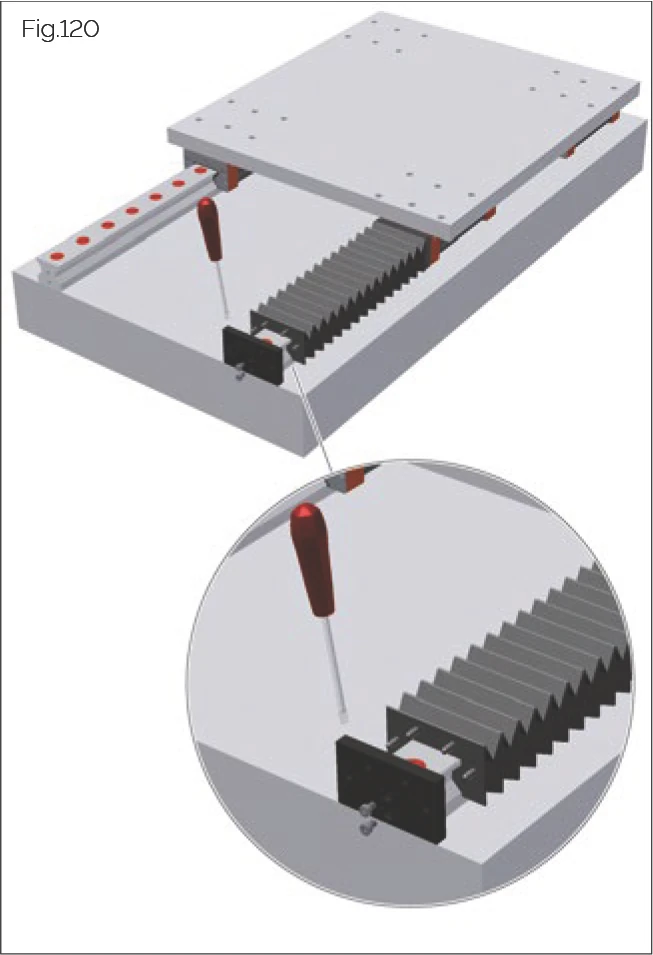
Fig.120
Replacing Bellows
- Use a flat-head screwdriver to loosen the bellows from the fastening plate.
- Loosen the fastening screws on the end plate.
- Remove the end plate.
- Clean the guideway.
- Check guideway plugs and cover strips for damage.
- Install the new pre-assembled bellows (with frame) onto the guideway.
- Snap the rivets at the bellows end into the corresponding holes on the adapter plate.
- Install the end plate.
- Snap the rivets at the bellows end into the corresponding holes on the adapter plate.
- Check whether the bellows is correctly positioned and has freedom of movement.
9.7 Spare Parts - Availability
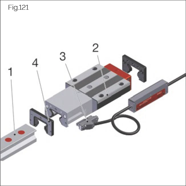
Fig.121
All precision-machined guideways in the MONORAIL MR, BM, and AMS product lines consist of four main subassemblies:
- Guideway
- Housing (with read head housing if applicable)
- AMS sensor unit
- Accessories
These subassemblies may lead to new structural versions due to technical improvements. This means that the internal construction of subassemblies may change with technology, material usage, quantity, and interaction of constituent parts.
SCHNEEBERGER commits to providing compatible complete subassemblies after delivery of the MONORAIL system, and therefore maintaining availability of complete subassemblies that are also compatible. Maintenance provides fixed service availability for all products without affecting availability. Parts from these subassemblies are only maintained and provided for up to 1 year before new subassemblies are introduced. This means subassemblies replaced by new structural versions are discontinued 1 year before expiration.
For complete subassemblies, SCHNEEBERGER provides compatible subassemblies that are identical in mechanical geometry for up to 10 years after the product is discontinued from the market. Any exceptions will be communicated individually.
Chapter 10 - Disposal
NOTE: Products and packaging materials, including plastics, metals, batteries, electronic components, wood, and lubricants, should be disposed of or recycled by the operator in accordance with locally applicable national or regional regulations.
Chapter 11 - Troubleshooting the AMS Measuring System
Operating State Display
The AMSA 3B, AMSA 4B, AMSD 3B/4B, and AMSABS measuring system versions are fitted with a service LED in the electronics housing of the read head that displays the different measuring system operating states.
| LED | Error | Repair |
|---|---|---|
| Red continuous | Encoder defective, internal hardware error | Replace sensor |
| Red flickering | External power supply outside tolerance | Check power cable from controller |
| Red/green flickering | Internal sensor signal too low (< 60%) | Remove dirt: Read head, receiving housing, and measuring scale must be cleaned. Check lubrication line connection. Replace read head. |
| Red/green flashing | Internal sensor signal too high (> 140%) | Check lubrication line connection. Replace read head. |
| Green flickering | Encoder damaged, internal sensor voltage > 5V | Replace encoder |
| Green flashing | Encoder damaged, internal sensor voltage < 0.6V | Replace encoder |
| Red flashing | Not referenced, absolute position incorrect | Repeat referencing |
| Green + red flashes | Backup battery empty | Replace battery |
| Red + green flashes | At least 1 CNC error detected | Fix controller error as required |
| Red + green flashes | Setting up DRIVE-CLiQ communication | No action required |
| Green continuous | System is working normally | No action required |