Correct design is the foundation for ensuring long-term, reliable bearing operation. The content of this page is based on the official myonic technical catalogue (page 28) and details the geometric parameters and structural requirements that must be strictly observed during the design phase.
Design errors may lead to (per the official breakdown):
- The bearing cannot seat fully against the shoulder, so its axial position is not stable
- The bearing rings deform or shift under load
- The housing shoulder contacts the inner ring, or the shaft shoulder contacts the outer ring, causing rotational interference
- Inability to install or remove the bearing correctly
1. Key Design Parameter Definitions
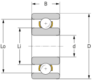
To ensure correct installation and operation of the bearing, the design of the shaft and the housing seat must strictly adhere to the following dimensional parameters (see the product tables):
| Symbol | Definition |
|---|---|
| d | Bearing inner diameter |
| D | Bearing outside diameter |
| B | Bearing width |
| Li | Minimum permissible shoulder diameter of the housing seat |
| Lo | Maximum permissible shoulder diameter of the shaft |
| r max | Maximum permissible rounding radius of the shaft or housing seat |
| h min | Minimum permissible shoulder height of the shaft or housing seat |
2. Please Avoid the Following Designs
Refer to the official illustrations, Figures 1 – 4. The following are common design errors:
Figure 1 Rounding radius too large
Error: The rounding radius r of the shaft or housing seat is larger than the bearing's r max.
Consequence: The bearing cannot seat against the shoulder, so its axial position is not stable; forcing it into place deforms the bearing ring.
Figure 2 Insufficient shoulder height
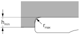
Error: The height of the shoulder or retaining ring is lower than h min.
Consequence: The bearing's axial position becomes unstable, and the ring is at risk of deforming.
Figure 3 Housing seat shoulder diameter too small

Error: The housing seat shoulder diameter De is smaller than Li.
Consequence: The housing seat shoulder contacts the rotating inner ring, causing rotational interference.
Figure 4 Shaft shoulder diameter too large
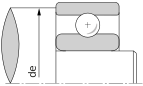
Error: The shaft shoulder diameter De is larger than the specified Lo.
Consequence: The shaft shoulder contacts the face of the stationary outer ring, causing rotational interference.
3. Please Ensure the Following Designs
A correct design must not only avoid the errors above but also account for the load path during installation and for ease of future maintenance (refer to the official illustrations, Figures 6 – 9).
Figure 6 Insufficient shoulder height — use a ground thrust ring
If design constraints mean the shoulder height cannot reach h min, a ground thrust ring should be inserted between the shoulder and the bearing to ensure an adequate axial support area.
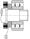
Figure 7 Load path during installation/removal
Take extra care when installing or removing radial bearings:
- Avoid transmitting force through the shaft to the bearing at the other end of the shaft.
- The bearing being installed must also be protected — the balls must not be subjected to load or impact.

Design for Disassembly
Miniature bearings are usually a very tight fit, so the design must consider how the bearing will later be removed without damaging the surrounding components.
Figure 8 Machine an extraction groove

Machine an extraction groove into the shoulder of the shaft or housing seat so the claws of a puller tool can engage.
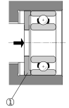
Figure 9 Force must act directly on the ring — use an intermediate ring for ease of removal
During installation or removal, the load must act directly on the bearing ring being installed or removed, avoiding transmission through the ball set. To make removal easier, an intermediate ring (marked 1 in the figure) should therefore be included.
Damage Caused by Incorrect Handling (Common Cases)
Even when the design parameters are correct, improper handling and installation can permanently damage the bearing. The following are typical examples of such damage:
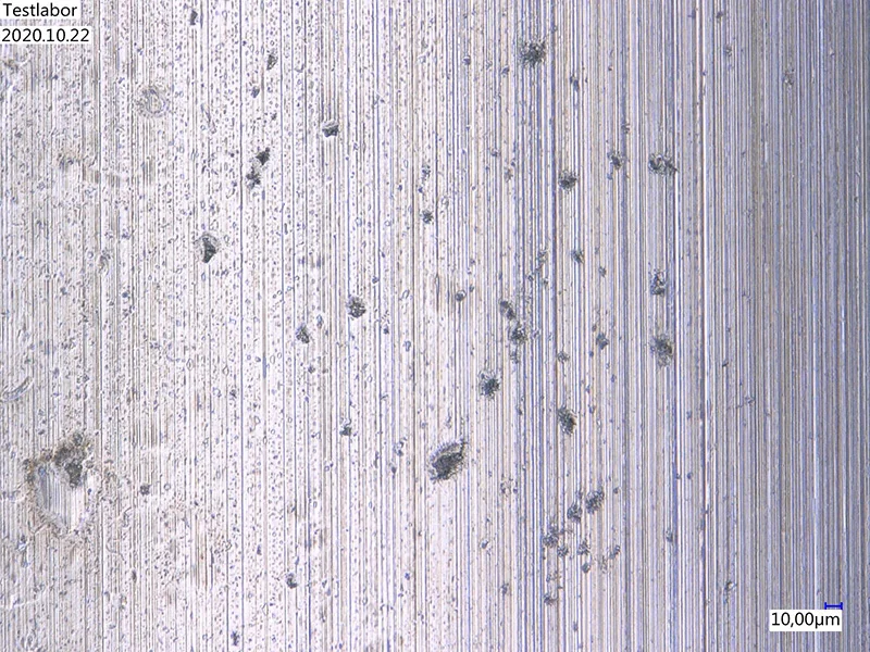
Raceway damage caused by foreign particles
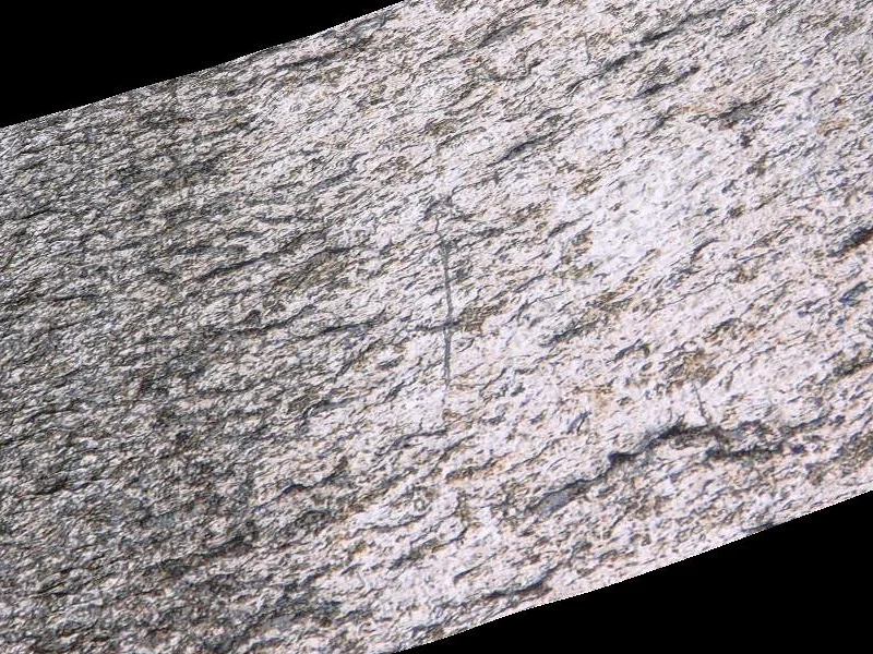
Damage caused by insufficient lubrication
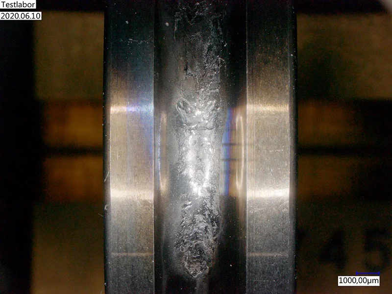
Raceway damage caused by overload
Technical Consultation
If you have any questions regarding design or installation, please contact the myonic technical support team.
Our engineers have extensive experience in miniature bearing applications and can provide professional technical guidance and customized solutions.