Rail Types MR S 35
| MR S 35-N | MR S 35-ND | MR S 35-NU | MR S 35-NUD | MR S 35-C |
|---|---|---|---|---|
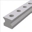 | 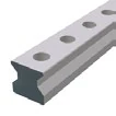 | 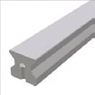 | 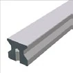 |  |
| Standard Top mounting | Standard, through-hardened Through-hardened | Bottom threaded hole Bottom mounting | Bottom threaded hole, through-hardened Through-hardened | Cover strip type For cover strip |
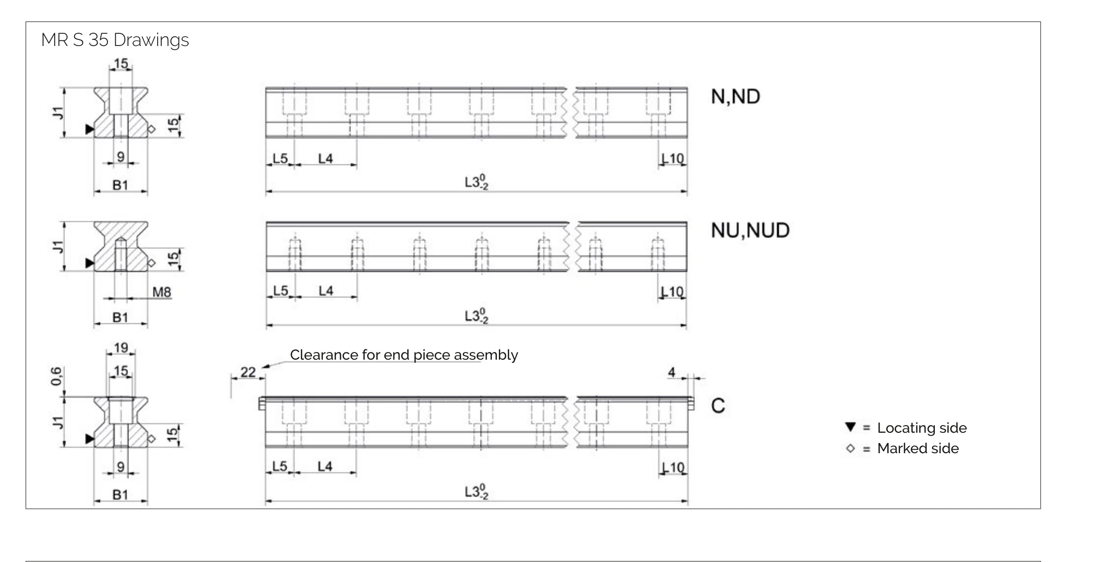
Rail Dimensional Drawing MR S 35
Rail Specifications MR S 35
| Parameter | MR S 35-N | MR S 35-ND | MR S 35-NU | MR S 35-NUD | MR S 35-C |
|---|---|---|---|---|---|
| Rail Width B1 (mm) | 34 | 34 | 34 | 34 | 34 |
| Rail Height J1 (mm) | 32 | 32 | 32 | 32 | 32 |
| Max. Single Length L3 (mm) | 6000 | 1500 | 6000 | 1500 | 6000 |
| Mounting Hole Pitch L4 (mm) | 40 | 40 | 40 | 40 | 40 |
| First/Last Hole Position L5/L10 (mm) | 18.5 | 18.5 | 18.5 | 18.5 | 18.5 |
| Weight per Meter (kg/m) | 6.5 | 6.5 | 7.1 | 7.1 | 6.3 |
Model Designations
- N = Standard (top mounting)
- ND = Standard, through-hardened
- NU = Bottom threaded hole (bottom mounting)
- NUD = Bottom threaded hole, through-hardened
- C = Cover strip type (for cover strip)
Carriage Types MR W 35
| MR W 35-A | MR W 35-B | MR W 35-C | MR W 35-D | MR W 35-E | MR W 35-F | MR W 35-G |
|---|---|---|---|---|---|---|
 |  | 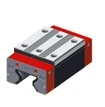 | 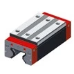 | 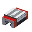 | 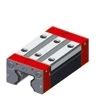 |  |
| Standard Standard | Standard long Standard long | High/flat High/flat | High/flat long High/flat long | Side fixing Side fixing | Flat Flat | Flat long Flat long |
Carriage Dimensional Drawing MR W 35
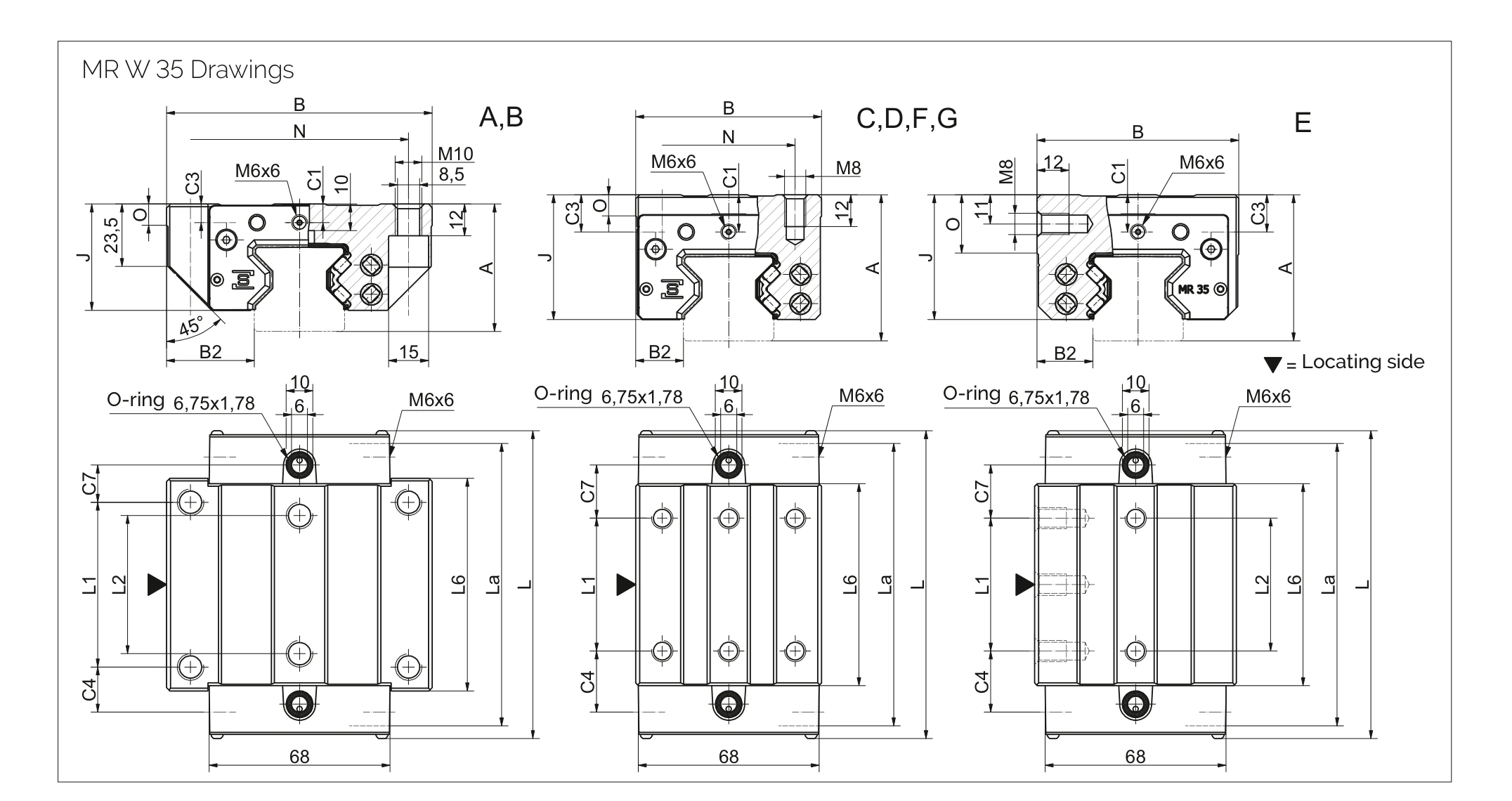
Carriage Specifications MR W 35
| Parameter | MR W 35-A | MR W 35-B | MR W 35-C | MR W 35-D | MR W 35-E | MR W 35-F | MR W 35-G |
|---|---|---|---|---|---|---|---|
| System Height A (mm) | 48 | 48 | 55 | 55 | 55 | 48 | 48 |
| Carriage Width B (mm) | 100 | 100 | 70 | 70 | 76 | 70 | 70 |
| Reference Distance B2 (mm) | 33 | 33 | 18 | 18 | 21 | 18 | 18 |
| Front Center Lube Port C1 (mm) | 7 | 7 | 14 | 14 | 14 | 7 | 7 |
| Side Lube Port Position C3 (mm) | 7 | 7 | 14 | 14 | 14 | 7 | 7 |
| Side Lube Port Position (2nd) C4 (mm) | 17 | 30.5 | 23 | 25.5 | 23 | 23 | 25.5 |
| Top Lube Port Position C7 (mm) | 14 | 27.5 | 20 | 22.5 | 20 | 20 | 22.5 |
| Carriage Height J (mm) | 40 | 40 | 47 | 47 | 47 | 40 | 40 |
| Carriage Length L (mm) | 116 | 143 | 116 | 143 | 116 | 116 | 143 |
| Transverse Wiper Distance La (mm) | 111 | 138 | 111 | 138 | 111 | 111 | 138 |
| Mounting Hole Pitch L1 (mm) | 62 | 62 | 50 | 72 | 50 | 50 | 72 |
| Mounting Hole Pitch L2 (mm) | 52 | 52 | — | — | 50 | — | — |
| Steel Body Length L6 (mm) | 80 | 103 | 76 | 103 | 76 | 76 | 103 |
| Mounting Hole Pitch N (mm) | 82 | 82 | 50 | 50 | — | 50 | 50 |
| Reference Height O (mm) | 8 | 8 | 8 | 8 | 22 | 8 | 8 |
Rigidity Curves and Load Rating Diagrams
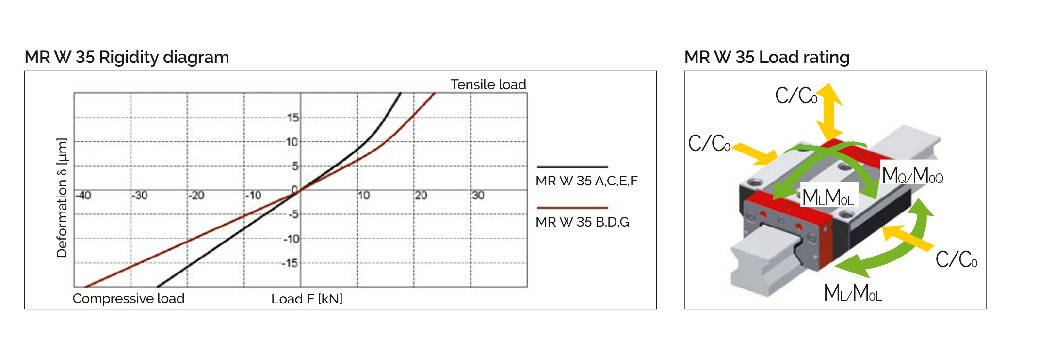
Load Ratings
| Parameter | MR W 35-A | MR W 35-B | MR W 35-C | MR W 35-D | MR W 35-E | MR W 35-F | MR W 35-G |
|---|---|---|---|---|---|---|---|
| Static Load Capacity C₀ (N) | 93400 | 128500 | 93400 | 128500 | 93400 | 93400 | 128500 |
| Dynamic Load Capacity C₁₀₀ (N) | 52000 | 71500 | 52000 | 71500 | 52000 | 52000 | 71500 |
| Static Cross Moment Capacity M₀Q (Nm) | 2008 | 2762 | 2008 | 2762 | 2008 | 2008 | 2762 |
| Static Longitudinal Moment Capacity M₀L (Nm) | 1189 | 2214 | 1189 | 2214 | 1189 | 1189 | 2214 |
| Dynamic Cross Moment Capacity MQ (Nm) | 1118 | 1537 | 1118 | 1537 | 1118 | 1118 | 1537 |
| Dynamic Longitudinal Moment Capacity ML (Nm) | 662 | 1232 | 662 | 1232 | 662 | 662 | 1232 |
| Carriage Weight (kg) | 1.6 | 2.2 | 1.5 | 2.0 | 1.8 | 1.2 | 1.6 |
Load Rating Definitions
- C₀ = Static load capacity - Maximum allowable load causing permanent deformation
- C₁₀₀ = Dynamic load capacity - Load for 100 km travel life
- M₀Q / MQ = Cross moment - Rotation around travel axis
- M₀L / ML = Longitudinal moment - Rotation around vertical axis
Available Options
Based on the Available options icon bar in the catalogue.
Common to Rails and Carriages
Accuracy Classes
 | G0 | Highly accurate |
 | G1 | Very accurate |
 | G2 | Accurate |
 | G3 | Standard |
Reference Side
 | R1 | Reference bottom |
 | R2 | Reference top |
Coating
 | CN | None |
 | CH | Hard chromium |
Rails
Straightness
 | KC | Standard |
Carriages
Preload Classes
 | V1 | Low |
 | V2 | Medium |
 | V3 | High |
Lubrication Ports
 | S10 | Left center |
 | S20 | Right center |
 | S11 | Top left |
 | S21 | Top right |
 | S12 | Lower left side |
 | S22 | Lower right side |
 | S13 | Upper left side |
 | S23 | Upper right side |
 | S32 | Left side |
 | S42 | Right side |
| S99 | All end-face ports closed with threaded plugs | |
| S98 | All side ports closed with threaded plugs |
Lubrication as Delivered
 | LN | Oil protect |
 | LG | Grease protect |
 | LV | Full greasing |
Order Code Examples
Rail Order Code
MR S 35-N-G1-KC-R1-918-19-19-CN
- MR S 35 = MONORAIL Rail Size 35
- N = Standard type
- G1 = Very accurate
- KC = Standard straightness
- R1 = Reference at bottom
- 918 = Rail length 918mm
- 19-19 = First/last hole positions
- CN = No coating (not chrome-plated; hard chromium is CH)
Carriage Order Code
MR W 35-B-G1-V3-R1-CN-S10-LN
- MR W 35 = MONORAIL Carriage Size 35
- B = Standard long type
- G1 = Very accurate
- V3 = High preload (13% C₁₀₀)
- R1 = Reference at bottom
- CN = No coating (not chrome-plated; hard chromium is CH)
- S10 = Lubrication port at front left center
- LN = Oil protect