Drawing
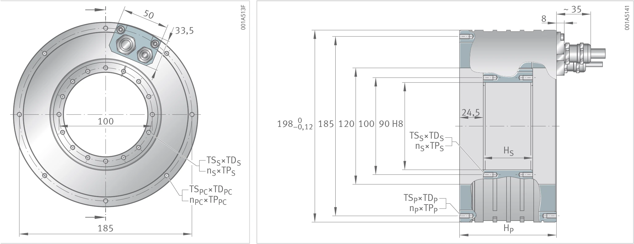
RIB11-3P-120xH drawing — stator (primary part) height HP, rotor (secondary part) height HS, outer diameter 185, inner diameter 90 H8. Includes the stator/rotor thread hole distribution (TS×TD, n×TP) and the cable outlet position.
Description
RIB is an internal-running permanent-magnet synchronous torque motor. The stator is a water-cooled, laminated, fully encapsulated iron core; the rotor is a steel ring with permanent magnets bonded radially onto the steel ring, which provides the magnetic return path. The rotor can be centred from either side of the inner diameter and fixed at the end face. The RIB11-3P-120xH series is divided by active height into 6 sizes from 120×25 to 120×150.
Geometric Data
Notes
Tolerance range ±10%. In the type designation, D×H represents "effective air-gap diameter × active height" (unit: mm).
| Geometric data | Symbol | Unit | 120×25 | 120×50 | 120×75 | 120×100 | 120×125 | 120×150 |
|---|---|---|---|---|---|---|---|---|
| Mass, secondary part | mS | kg | 0.9 | 1.7 | 2.6 | 3.4 | 4.3 | 5.1 |
| Mass, primary part | mP | kg | 7.9 | 10.8 | 13.7 | 17.2 | 20.4 | 23.6 |
| Height, secondary part | HS | mm | 26 | 51 | 76 | 101 | 126 | 151 |
| Height, primary part | HP | mm | 80 | 100 | 120 | 150 | 175 | 200 |
| Thread, secondary part | TSS×TDS | – | M5×10 | M5×10 | M5×10 | M6×10 | M6×10 | M6×10 |
| Thread, secondary part, number×pitch | nS×TPS | ° | 16×22.5 | 16×22.5 | 16×22.5 | 16×22.5 | 16×22.5 | 16×22.5 |
| Thread, primary part, cable side | TSPC×TDPC | – | M5×10 | M5×10 | M5×10 | M5×10 | M5×10 | M5×10 |
| Thread, primary part, cable side, number×pitch | nPC×TPPC | ° | 8×45 | 8×45 | 8×45 | 15×22.5 | 15×22.5 | 15×22.5 |
| Thread, primary part | TSP×TDP | – | M5×10 | M5×10 | M5×10 | M5×10 | M5×10 | M5×10 |
| Thread, primary part, number×pitch | nP×TPP | ° | 8×45 | 8×45 | 8×45 | 16×22.5 | 16×22.5 | 16×22.5 |
Performance Data
Notes
Tolerance range ±10%. Each column is a "size × winding design" combination, with winding design codes such as Z0.7, Z1.5, Z1.4, Z2.9. Nominal feed temperature of the cooling water +20 °C.
| Performance data | Symbol | Unit | 120×25 Z0.7 | 120×25 Z1.5 | 120×50 Z1.5 | 120×75 Z1.4 | 120×75 Z2.9 | 120×100 Z1.4 | 120×100 Z2.9 | 120×125 Z1.4 | 120×125 Z2.9 | 120×150 Z1.5 | 120×150 Z2.9 |
|---|---|---|---|---|---|---|---|---|---|---|---|---|---|
| Torques | |||||||||||||
| Ultimate torque | Tu | Nm | 68 | 68 | 157 | 236 | 236 | 314 | 314 | 393 | 393 | 471 | 471 |
| Peak torque | Tp | Nm | 62 | 62 | 139 | 208 | 208 | 277 | 277 | 346 | 346 | 416 | 416 |
| Continuous torque, cooled | Tcw | Nm | 32 | 32 | 77 | 126 | 126 | 171 | 171 | 219 | 219 | 250 | 264 |
| Continuous torque, not cooled | Tc | Nm | 10 | 10 | 26 | 45 | 45 | 62 | 62 | 80 | 80 | 92 | 98 |
| Stall torque, cooled | Tsw | Nm | 25 | 25 | 59 | 97 | 97 | 131 | 131 | 167 | 167 | 191 | 202 |
| Cogging torque | Tcog | Nm | 0.21 | 0.21 | 0.42 | 0.63 | 0.63 | 0.84 | 0.84 | 1.05 | 1.05 | 1.26 | 1.26 |
| Speeds | |||||||||||||
| Limiting speed at Ip eff and UDCL | nlp | min⁻¹ | 468 | 1002 | 509 | 298 | 645 | 222 | 494 | 172 | 395 | 154 | 328 |
| Knee speed | nlw | min⁻¹ | 886 | 1843 | 849 | 479 | 1005 | 356 | 758 | 276 | 598 | 260 | 495 |
| Rated speed S1, cooled | nlwS1 | min⁻¹ | 682 | 682 | 682 | 479 | 682 | 356 | 682 | 276 | 598 | 260 | 495 |
| Currents | |||||||||||||
| Effective ultimate current | Iu eff | A | 18 | 36.1 | 36.1 | 32.2 | 64.5 | 32.2 | 64.5 | 32.2 | 64.5 | 36.1 | 64.5 |
| Effective peak current | Ip eff | A | 14.4 | 28.8 | 28.8 | 25.8 | 51.6 | 25.8 | 51.6 | 25.8 | 51.6 | 28.8 | 51.6 |
| Effective continuous current, cooled | Icw eff | A | 6.4 | 12.7 | 14.1 | 13.7 | 27.5 | 13.9 | 27.9 | 14.3 | 28.6 | 15.2 | 28.8 |
| Effective continuous current, not cooled | Ic eff | A | 1.9 | 3.7 | 4.7 | 4.8 | 9.6 | 5 | 10 | 5.1 | 10.2 | 5.5 | 10.4 |
| Effective stall current, cooled | Isw eff | A | 4.8 | 9.6 | 10.6 | 10.3 | 20.6 | 10.5 | 20.9 | 10.7 | 21.4 | 11.4 | 21.6 |
| Power losses | |||||||||||||
| Power loss at Tp | Plp | W | 2472 | 2472 | 3794 | 4425 | 4425 | 5454 | 5454 | 6483 | 6483 | 8393 | 7512 |
| Power loss at Tcw | Plw | W | 651 | 651 | 1222 | 1697 | 1697 | 2153 | 2153 | 2688 | 2688 | 3158 | 3158 |
| Power loss at Tc | Plc | W | 41 | 41 | 102 | 153 | 153 | 205 | 205 | 256 | 256 | 307 | 307 |
| Electrical characteristic values | |||||||||||||
| DC link voltage | UDCL | V | 600 | 600 | 600 | 600 | 600 | 600 | 600 | 600 | 600 | 600 | 600 |
| Electrical resistance, phase to phase | R20 | Ω | 7.9 | 2 | 3 | 4.4 | 1.1 | 5.5 | 1.4 | 6.5 | 1.6 | 6.7 | 1.9 |
| Inductance, phase to phase | L | mH | 51.4 | 12.8 | 23.5 | 42.8 | 10.7 | 54.1 | 13.5 | 66.2 | 16.5 | 62.1 | 19.4 |
| Back EMF constant, phase to phase | kû | V/(rad/s) | 4.2 | 2.1 | 4.6 | 7.7 | 3.8 | 10.2 | 5.1 | 12.8 | 6.4 | 13.7 | 7.7 |
| General characteristic values | |||||||||||||
| Number of pole pairs | P | – | 11 | 11 | 11 | 11 | 11 | 11 | 11 | 11 | 11 | 11 | 11 |
| Motor constant | km | Nm/√W | 1.51 | 1.51 | 2.62 | 3.63 | 3.63 | 4.36 | 4.36 | 5 | 5 | 5.28 | 5.58 |
| Torque constant | kT | Nm/A | 5.2 | 2.6 | 5.6 | 9.4 | 4.7 | 12.5 | 6.2 | 15.6 | 7.8 | 16.8 | 9.4 |
| Motor temperature switch-off threshold | ϑPTC | °C | 110 | 110 | 110 | 110 | 110 | 110 | 110 | 110 | 110 | 110 | 110 |
| Axial attraction | Fa | kN | 0.16 | 0.16 | 0.16 | 0.16 | 0.16 | 0.16 | 0.16 | 0.16 | 0.16 | 0.16 | 0.16 |
| Radial attraction | Fr | kN/mm | 0.5 | 0.5 | 0.9 | 1.4 | 1.4 | 1.8 | 1.8 | 2.2 | 2.2 | 2.7 | 2.7 |
| Moment of inertia, secondary part | J | kg·m² | 0.0023 | 0.0023 | 0.0046 | 0.0069 | 0.0069 | 0.0091 | 0.0091 | 0.0114 | 0.0114 | 0.0136 | 0.0136 |
| Cooling conditions | |||||||||||||
| Volume flow | dV/dt | l/min | 1.9 | 1.9 | 3.5 | 4.9 | 4.9 | 6.2 | 6.2 | 7.7 | 7.7 | 9 | 9 |
| Nominal feed temperature | ϑnf | °C | 20 | 20 | 20 | 20 | 20 | 20 | 20 | 20 | 20 | 20 | 20 |
| Cooling water temperature difference | ∆ϑ | K | 5 | 5 | 5 | 5 | 5 | 5 | 5 | 5 | 5 | 5 | 5 |
Note: Tolerance range of all values ±10%. Binding data and drawings will be made available by agreement; we recommend obtaining support from our engineers in the motor design phase. Subject to change without notice.