Parallelism of the Reference and Locating Surfaces
They must be compatible with those of the linear guideway (also applies when using linear guideways with recirculating units):
| NQ | Normal quality |
| SQ | Special quality |
| SSQ | Super special quality |
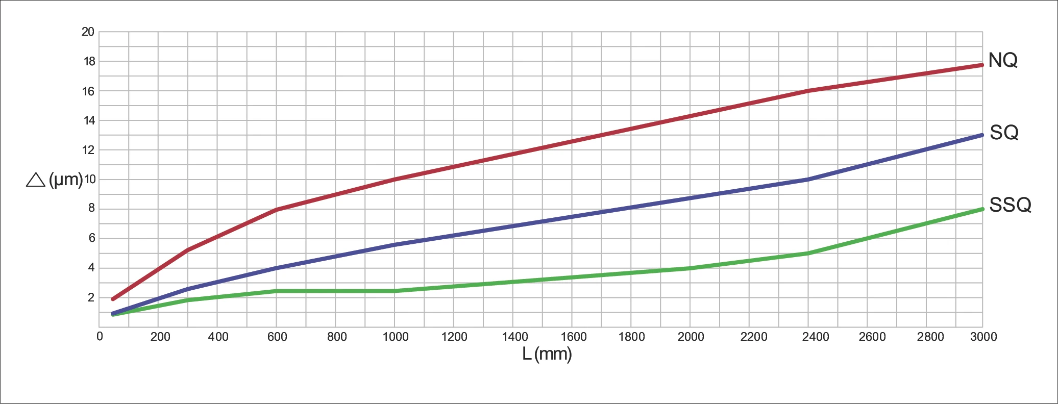
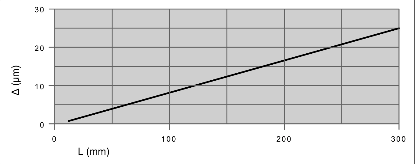
Parallelism deviation Δ (µm) vs. guideway length L (mm)
Surface Quality
The accuracy of the application critically determines the required surface quality of the reference and locating surfaces.
- For high-precision applications they must demonstrate a maximum Ra value of 0.4.
- An Ra value of 1.6 may not be exceeded for standard applications.
Angular Error
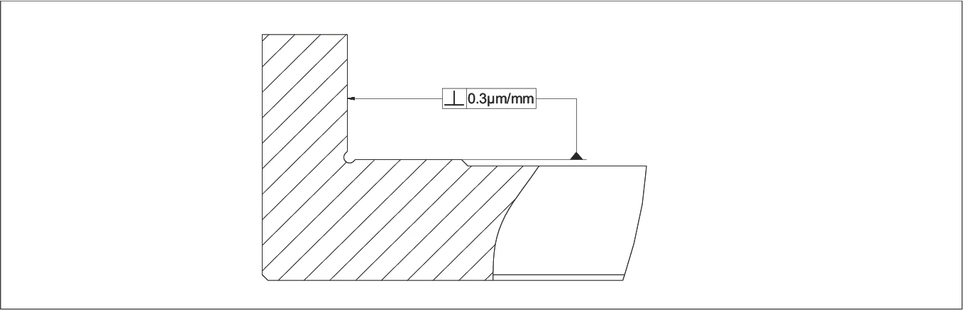
The angular errors for the supporting and locating surface should not exceed 0.3 µm/mm.
Height Offset for Linear Guideways
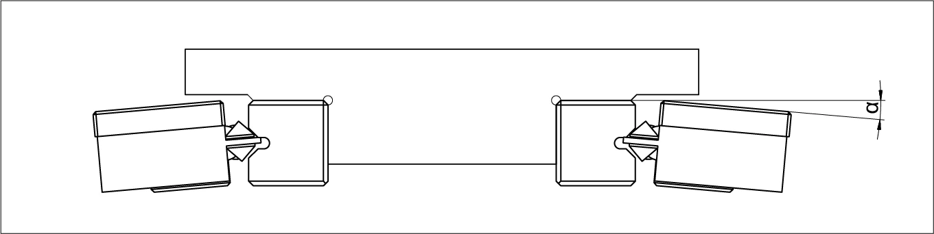
The angular errors resulting from height offset and/or elastic deformations may not exceed the following values:
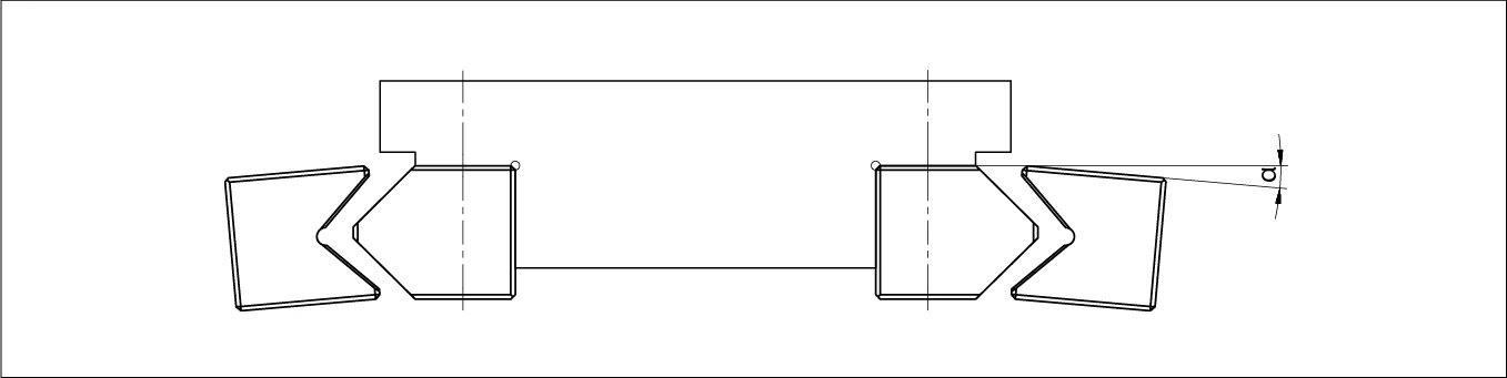
| Balls or rollers | 0.3 µm/mm |
| Needles | 0.1 µm/mm |
Parallelism of the Supporting and Locating Surfaces in the Case of the Recirculating Unit
The parallelism of the supporting and locating surfaces in relation to the mating track can be derived from the diagram below:
Height Offset for Recirculating Units
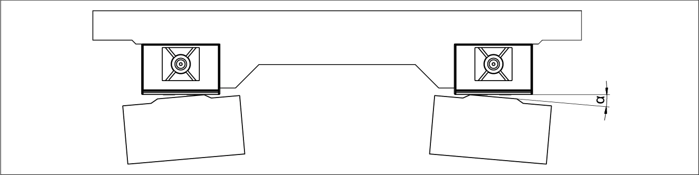
The angular errors resulting from height offset and/or elastic deformations may not exceed the following values:
| For types SK, SKD and SKC | 3.0 µm/mm |
| For type SR | 0.3 µm/mm |
| For type NRT | 0.3 µm/mm |
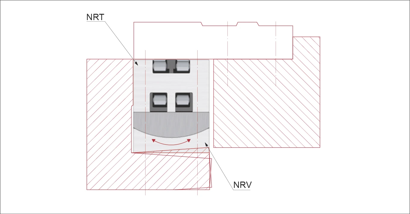
Combination of Recirculating Unit NRT with Preload Wedge NRV
So that straight run-off is guaranteed, the recirculating unit NRT must always be oriented against the locating surface.
The preload wedge NRV should be aligned opposite the recirculating unit and compensates for angular errors.