15.3 Reference Height and Corner Radii
Observance of the following height specifications for the reference surfaces guarantees secure absorption of force and sufficient clearance for the carriages. The carriages and guide rails feature a chamfer on the edges of the reference surfaces. The corner radii specified in the following tables are maximum values which ensure that carriages and guide rails contact the mounting surfaces correctly.
The reference side of the carriage is opposite the carriage side with the company logo / type designation. The guideway can be located on both sides.
The dimensions listed for the reference surface should be applied to ensure optimal alignment of the guideway and an easy installation.
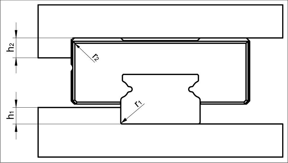
Reference surface and corner radii diagram
MINIRAIL and MINISCALE PLUS
| Rail size | h₁ | r₁max | r₂max | h₂ |
|---|---|---|---|---|
| 7 | 1.2 | 0.2 | 0.3 | 2.5 |
| 9 | 1.5 | 0.3 | 0.4 | 3 |
| 12 | 2.5 | 0.4 | 0.4 | 4 |
| 15 | 3.5 | 0.5 | 0.5 | 5 |
| 14 | 1.8 | 0.2 | 0.4 | 2 |
| 18 | 3 | 0.3 | 0.5 | 3 |
| 24 | 3.5 | 0.4 | 0.5 | 4 |
| 42 | 3.5 | 0.5 | 0.6 | 5 |
MINISLIDE
| Rail size | h₁ | r₁max | r₂max | h₂ |
|---|---|---|---|---|
| 4 | 0.2 | 0.1 | 0.1 | 1.2 |
| 5 | 0.4 | 0.2 | 0.1 | 1.8 |
| 7 | 1.0 | 0.2 | 0.3 | 2.5 |
| 9 | 1.5 | 0.3 | 0.4 | 3 |
| 12 | 2.5 | 0.4 | 0.4 | 4 |
| 15 | 3.0 | 0.5 | 0.5 | 5 |