10.2 MINISCALE PLUS Technical Information
10.2.1 MINISCALE PLUS Performance Parameters
| Maximum acceleration | 300 m/s² |
|---|---|
| Maximum speed | 5 m/s analog, 3.2 m/s digital |
| Preload class | V1 preload 0 to 0.03 C (C = dynamic load capacity) |
| Accuracy class | G1 |
| Material |
|
| Application range |
|
| Resolution | TTL output 0.1 µm (3) (optional: 1 µm / 10 µm) |
| Accuracy (2) | 1000 mm ±5 µm (4) |
| Repeatability (2) |
Unidirectional ±0.1 µm Bidirectional ±0.2 µm (at resolution 0.1 µm) |
| Dimensional scale |
Pitch 100 µm Maximum length 1000 mm Expansion coefficient 11.7 × 10⁻⁶K-1 |
| Supply voltage | 5 V DC ±5 % |
| Current consumption (typical) | 60 mA (analog) / 90 mA (digital) |
| Output signal |
Analog: 1 Vpp (at 120 Ω) Digital: TTL according to RS 422 standard |
| Signal format | Differential sin/cos analog signals with reference pulse or digital incremental signals with reference pulse |
(1) The standard lubrication covers a temperature range of -20 °C to +80 °C. Lubricants for other temperatures are available from SCHNEEBERGER on request.
(2) Values apply at room temperature of 20 °C (68 °F).
(3) Note the high signal frequency at high resolution and high speed.
(4) Linearity agreement available on request
10.2.2 Dimension Tables, Load Capacities, and Moment Loads for Standard Width MINISCALE PLUS
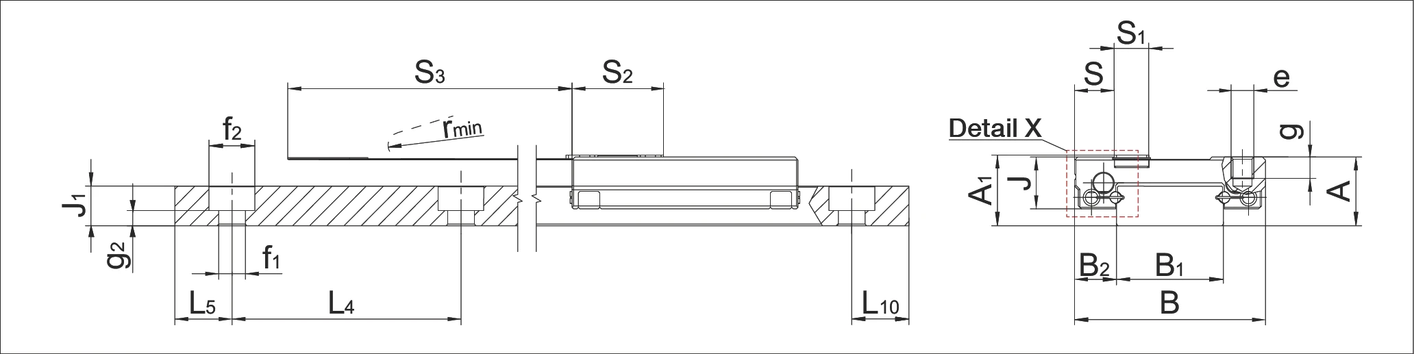
MINISCALE PLUS dimension diagram
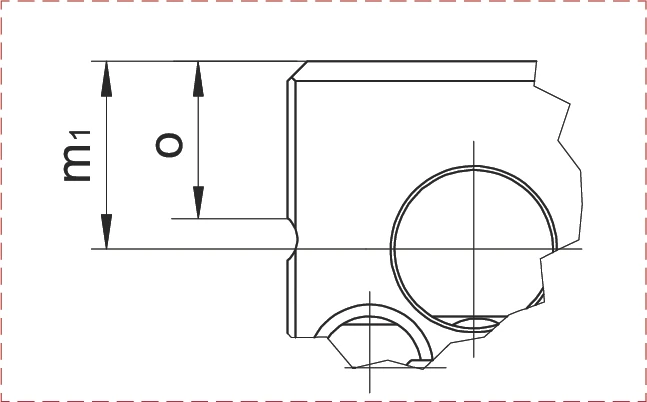
Detail X - carriage cross-section dimensions (m1 and o)
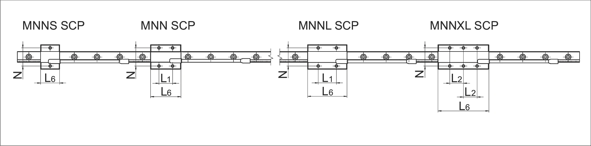
Carriage types - MNNS SCP, MNN SCP, MNNL SCP, MNNXL SCP
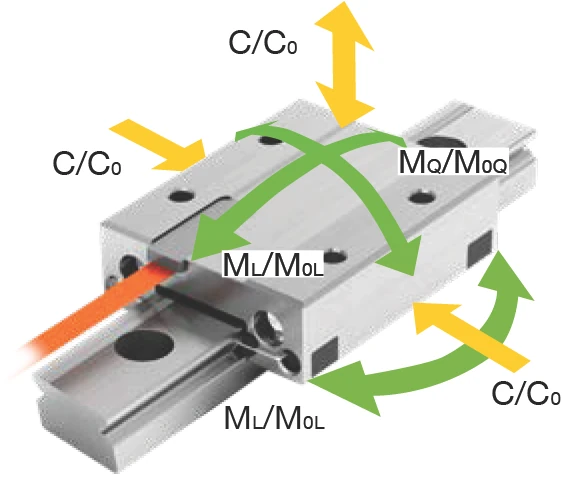
Load and moment load directions (C/C₀, ML/M₀L, Ma/M₀a)
Standard size 7 and 9
| Name | Standard size 7 | Standard size 9 | |||||||||
|---|---|---|---|---|---|---|---|---|---|---|---|
| Guideway | MNNS SCP | MNN SCP | MNNL SCP | MNNXL SCP | Guideway | MNNS SCP | MNN SCP | MNNL SCP | MNNXL SCP | ||
| Dimensions (mm) | A | - | 8 | 8 | 8 | 8 | - | 10 | 10 | 10 | 10 |
| A1 | - | 9.2 | 9.2 | 9.2 | 9.2 | - | 10 | 10 | 10 | 10 | |
| B | - | 17 | 17 | 17 | 17 | - | 20 | 20 | 20 | 20 | |
| B1 | 7 | - | - | - | - | 9 | - | - | - | - | |
| B2 | - | 5 | 5 | 5 | 5 | - | 5.5 | 5.5 | 5.5 | 5.5 | |
| J | - | 6.5 | 6.5 | 6.5 | 6.5 | - | 8 | 8 | 8 | 8 | |
| J1 | 4.5 | - | - | - | - | 5.5 | - | - | - | - | |
| L1 | - | - | 8 | 13 | 20 | - | - | 10 | 16 | 26 | |
| L2 | - | - | - | - | 10 | - | - | - | - | 13 | |
| L4 | 15 | - | - | - | - | 20 | - | - | - | - | |
| L5/L10 | 5 | - | - | - | - | 7.5 | - | - | - | - | |
| L6 | - | 16.1 | 22.1 | 29.6 | 38.6 | - | 19 | 29 | 37 | 47 | |
| N | - | 12 | 12 | 12 | 12 | - | 15 | 15 | 15 | 15 | |
| e | - | M2 | M2 | M2 | M2 | - | M3 | M3 | M3 | M3 | |
| f1 | 2.4 | - | - | - | - | 3.5 | - | - | - | - | |
| f2 | 4.2 | - | - | - | - | 6 | - | - | - | - | |
| g | - | 2.5 | 2.5 | 2.5 | 2.5 | - | 3 | 3 | 3 | 3 | |
| g2 | 2.2 | - | - | - | - | 2 | - | - | - | - | |
| m1 | - | 3.1 | 3.1 | 3.1 | 3.1 | - | 3.8 | 3.8 | 3.8 | 3.8 | |
| o | - | 2.5 | 2.5 | 2.5 | 2.5 | - | 3.1 | 3.1 | 3.1 | 3.1 | |
| s | - | 3.6 | 3.6 | 3.6 | 3.6 | - | 4.2 | 4.2 | 4.2 | 4.2 | |
| s1 | - | 5.5 | 5.5 | 5.5 | 5.5 | - | 5.5 | 5.5 | 5.5 | 5.5 | |
| s2 | - | 13.5 | 13.5 | 13.5 | 13.5 | - | 13.5 | 13.5 | 13.5 | 13.5 | |
| s3 | - | 75 | 75 | 75 | 75 | - | 75 | 75 | 75 | 75 | |
| rmin | - | 2 | 2 | 2 | 2 | - | 2 | 2 | 2 | 2 | |
| Load capacity (N) | C0 | - | 935 | 1560 | 2340 | 3275 | - | 1385 | 2770 | 3880 | 5270 |
| C | - | 645 | 925 | 1230 | 1550 | - | 1040 | 1690 | 2140 | 2645 | |
| Torque (Nm) | M0Q | - | 3.4 | 5.6 | 8.4 | 11.8 | - | 6.5 | 12.9 | 18.1 | 24.5 |
| M0L | - | 1.6 | 4.3 | 9.3 | 18 | - | 2.8 | 10.2 | 19.4 | 35.1 | |
| MQ | - | 2.3 | 3.3 | 4.4 | 5.6 | - | 4.8 | 7.9 | 9.9 | 12.3 | |
| ML | - | 1.1 | 2.5 | 4.9 | 8.5 | - | 2.1 | 6.2 | 10.7 | 17.6 | |
| Weights guideway (g/m), carriage (g) | 216 | 9 | 13 | 18 | 23 | 309 | 16 | 24 | 31 | 40 | |
Standard size 12 and 15
| Name | Standard size 12 | Standard size 15 | |||||||||
|---|---|---|---|---|---|---|---|---|---|---|---|
| Guideway | MNNS SCP | MNN SCP | MNNL SCP | MNNXL SCP | Guideway | MNNS SCP | MNN SCP | MNNL SCP | MNNXL SCP | ||
| Dimensions (mm) | A | - | 13 | 13 | 13 | 13 | - | 16 | 16 | 16 | 16 |
| A1 | - | 13 | 13 | 13 | 13 | - | 16 | 16 | 16 | 16 | |
| B | - | 27 | 27 | 27 | 27 | - | 32 | 32 | 32 | 32 | |
| B1 | 12 | - | - | - | - | 15 | - | - | - | - | |
| B2 | - | 7.5 | 7.5 | 7.5 | 7.5 | - | 8.5 | 8.5 | 8.5 | 8.5 | |
| J | - | 10 | 10 | 10 | 10 | - | 12 | 12 | 12 | 12 | |
| J1 | 7.5 | - | - | - | - | 9.5 | - | - | - | - | |
| L1 | - | - | 15 | 20 | 30 | - | - | 20 | 25 | 40 | |
| L2 | - | - | - | - | 15 | - | - | - | - | 20 | |
| L4 | 25 | - | - | - | - | 30 | - | - | - | - | |
| L5/L10 | 10 | - | - | - | - | 15 | - | - | - | - | |
| L6 | - | 20.9 | 33.4 | 43.4 | 55.9 | - | 28.7 | 40.7 | 55.7 | 70.7 | |
| N | - | 20 | 20 | 20 | 20 | - | 25 | 25 | 25 | 25 | |
| e | - | M3 | M3 | M3 | M3 | - | M3 | M3 | M3 | M3 | |
| f1 | 3.5 | - | - | - | - | 3.5 | - | - | - | - | |
| f2 | 6 | - | - | - | - | 6 | - | - | - | - | |
| g | - | 3.5 | 3.5 | 3.5 | 3.5 | - | 4 | 4 | 4 | 4 | |
| g2 | 3 | - | - | - | - | 5 | - | - | - | - | |
| m1 | - | 4.75 | 4.75 | 4.75 | 4.75 | - | 5.55 | 5.55 | 5.55 | 5.55 | |
| o | - | 3.9 | 3.9 | 3.9 | 3.9 | - | 4.9 | 4.9 | 4.9 | 4.9 | |
| s | - | 6.7 | 6.7 | 6.7 | 6.7 | - | 8.3 | 8.3 | 8.3 | 8.3 | |
| s1 | - | 5.5 | 5.5 | 5.5 | 5.5 | - | 5.5 | 5.5 | 5.5 | 5.5 | |
| s2 | - | 13.5 | 13.5 | 13.5 | 13.5 | - | 13.5 | 13.5 | 13.5 | 13.5 | |
| s3 | - | 75 | 75 | 75 | 75 | - | 75 | 75 | 75 | 75 | |
| rmin | - | 2 | 2 | 2 | 2 | - | 2 | 2 | 2 | 2 | |
| Load capacity (N) | C0 | - | 1735 | 3900 | 5630 | 7800 | - | 3120 | 5620 | 8740 | 11855 |
| C | - | 1420 | 2510 | 3240 | 4070 | - | 2435 | 3680 | 5000 | 6200 | |
| Torque (Nm) | M0Q | - | 10.6 | 23.8 | 34.4 | 47.6 | - | 23.7 | 42.7 | 66.4 | 90.1 |
| M0L | - | 3.6 | 16.3 | 32.9 | 61.8 | - | 9.4 | 28.1 | 65.5 | 118.6 | |
| MQ | - | 8.7 | 15.3 | 19.8 | 24.8 | - | 18.5 | 27.9 | 38.1 | 47.1 | |
| ML | - | 3 | 10.4 | 18.9 | 32.2 | - | 7.3 | 18.4 | 37.6 | 62 | |
| Weights guideway (g/m), carriage (g) | 598 | 29 | 47 | 63 | 81 | 996 | 56 | 81 | 114 | 146 | |
10.2.3 Dimension Tables, Load Capacities and Moment Loads for Wider MINISCALE PLUS
MINISCALE PLUS Wide dimension diagram
Detail X - carriage cross-section dimensions (m1 and o)
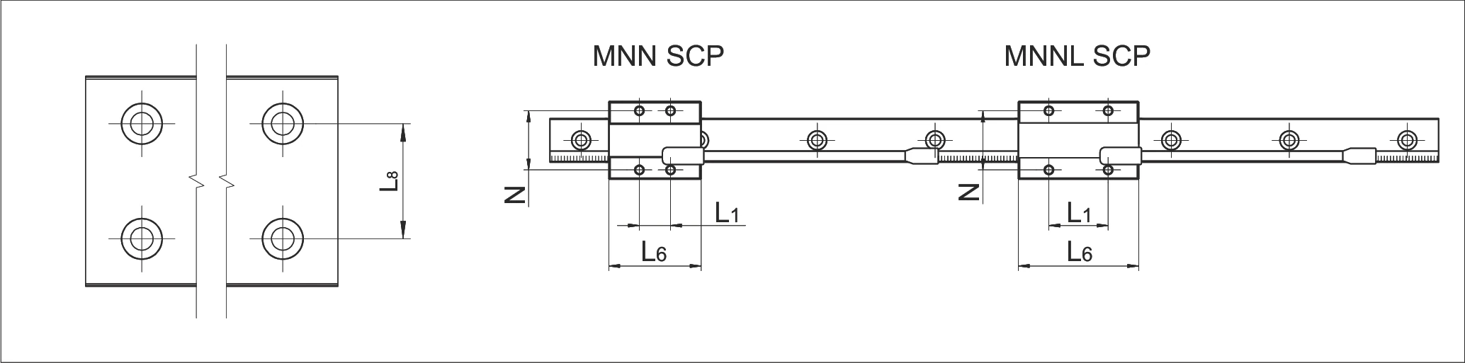
Carriage types - MNN SCP, MNNL SCP (Wide size available in two types only)
Load and moment load directions (C/C₀, ML/M₀L, Ma/M₀a)
Wide size 14 and 18
Note: Wide size is available in only 2 carriage types (MNN, MNNL).
| Name | Wide size 14 | Wide size 18 | |||||
|---|---|---|---|---|---|---|---|
| Guideway | MNN SCP | MNNL SCP | Guideway | MNN SCP | MNNL SCP | ||
| Dimensions (mm) | A | - | 9 | - | - | 12 | - |
| A1 | - | 10 | - | - | - | - | |
| B | - | 25 | - | - | 30 | - | |
| B1 | 14 | - | - | 18 | - | - | |
| B2 | - | 5.5 | - | - | 6 | - | |
| J | - | 6.8 | - | - | 8.5 | - | |
| J1 | 5.2 | - | - | 7 | - | - | |
| L1 | - | 10 | 19 | - | 12 | 24 | |
| L2 | - | - | - | - | - | - | |
| L4 | 30 | - | - | 30 | - | - | |
| L5/L10 | 10 | - | - | 10 | - | - | |
| L6 | - | 29.6 | 38.6 | - | 37 | 47 | |
| L8 | - | - | - | - | - | - | |
| N | - | 19 | - | - | 21 | - | |
| e | - | M3 | - | - | M3 | - | |
| f1 | 3.5 | - | - | 3.5 | - | - | |
| f2 | 6 | - | - | 6 | - | - | |
| g | - | 2.8 | - | - | 3 | - | |
| g2 | 2 | - | - | 2.5 | - | - | |
| m1 | - | 3.3 | - | - | 4.3 | - | |
| o | - | 2.2 | - | - | 3.1 | - | |
| s | - | 5.2 | - | - | 5.8 | - | |
| s1 | - | 5.5 | - | - | 5.5 | - | |
| s2 | - | 13.5 | - | - | 13.5 | - | |
| s3 | - | 75 | - | - | 75 | - | |
| rmin | - | 2 | - | - | 2 | - | |
| Load capacity (N) | C0 | - | 2340 | 3275 | - | 3880 | 5270 |
| C | - | 1230 | 1550 | - | 2140 | 2645 | |
| Torque (Nm) | M0Q | - | 16.6 | 23.3 | - | 35.5 | 48.2 |
| M0L | - | 9.3 | 18 | - | 19.4 | 35.1 | |
| MQ | - | 8.7 | 11 | - | 19.6 | 24.2 | |
| ML | - | 4.9 | 8.5 | - | 10.7 | 17.6 | |
| Weights guideway (g/m), carriage (g) | 518 | 25 | 33 | 915 | 47 | 60 | |
Wide size 24 and 42
| Name | Wide size 24 | Wide size 42 | |||||
|---|---|---|---|---|---|---|---|
| Guideway | MNN SCP | MNNL SCP | Guideway | MNN SCP | MNNL SCP | ||
| Dimensions (mm) | A | - | 14 | - | - | 16 | - |
| A1 | - | - | - | - | - | - | |
| B | - | 40 | - | - | 60 | - | |
| B1 | 24 | - | - | 42 | - | - | |
| B2 | - | 8 | - | - | 9 | - | |
| J | - | 10 | - | - | 12 | - | |
| J1 | 8.5 | - | - | 9.5 | - | - | |
| L1 | - | 15 | 28 | - | 20 | 35 | |
| L2 | - | - | - | - | - | - | |
| L4 | 40 | - | - | 40 | - | - | |
| L5/L10 | 15 | - | - | 15 | - | - | |
| L6 | - | 43.4 | 55.9 | - | 52.7 | 70.7 | |
| L8 | - | - | - | - | 23 | - | |
| N | - | 28 | - | - | 45 | - | |
| e | - | M3 | - | - | M4 | - | |
| f1 | 4.5 | - | - | 4.5 | - | - | |
| f2 | 8 | - | - | 8 | - | - | |
| g | - | 3.5 | - | - | 4.5 | - | |
| g2 | 4 | - | - | 5 | - | - | |
| m1 | - | 4.75 | - | - | 5.5 | - | |
| o | - | 3.9 | - | - | 4.9 | - | |
| s | - | 7.8 | - | - | 8.8 | - | |
| s1 | - | 5.5 | - | - | 5.5 | - | |
| s2 | - | 13.5 | - | - | 13.5 | - | |
| s3 | - | 75 | - | - | 75 | - | |
| rmin | - | 2 | - | - | 2 | - | |
| Load capacity (N) | C0 | - | 5630 | 7800 | - | 8110 | 11855 |
| C | - | 3240 | 4070 | - | 4750 | 6200 | |
| Torque (Nm) | M0Q | - | 68.2 | 94.4 | - | 171.2 | 250.2 |
| M0L | - | 32.9 | 61.8 | - | 56.8 | 118.6 | |
| MQ | - | 39.2 | 49.3 | - | 100.3 | 130.8 | |
| ML | - | 18.9 | 32.2 | - | 33.3 | 62 | |
| Weights guideway (g/m), carriage (g) | 1476 | 84 | 109 | 2828 | 169 | 231 | |
MINISCALE PLUS integrates the linear guideway and position measuring system, providing a complete motion control solution.
10.2.4 MINISCALE PLUS Components and Working Method
MINISCALE PLUS is an optical incremental measuring system consisting of the MINIRAIL guideway system and the following additional components:
- A Dimensional scale on the guideway
- B Optical sensor on the carriage
- C Flexible sensor printed circuit (must not be subjected to dynamic loads)
- D Interface module
The control cable E with D-Sub 9 connector must be provided by the customer; a flexible cable should be used where necessary.
Various construction types of the interface module are available. These are described in detail in the "Interface module" section.
A Flat Flex Cable (FFC) inserted between the flexible sensor printed circuit and the interface module allows flexible positioning of the interface module. The FFC is suitable for dynamic loads. (See chapter 10.2.8 for details.)
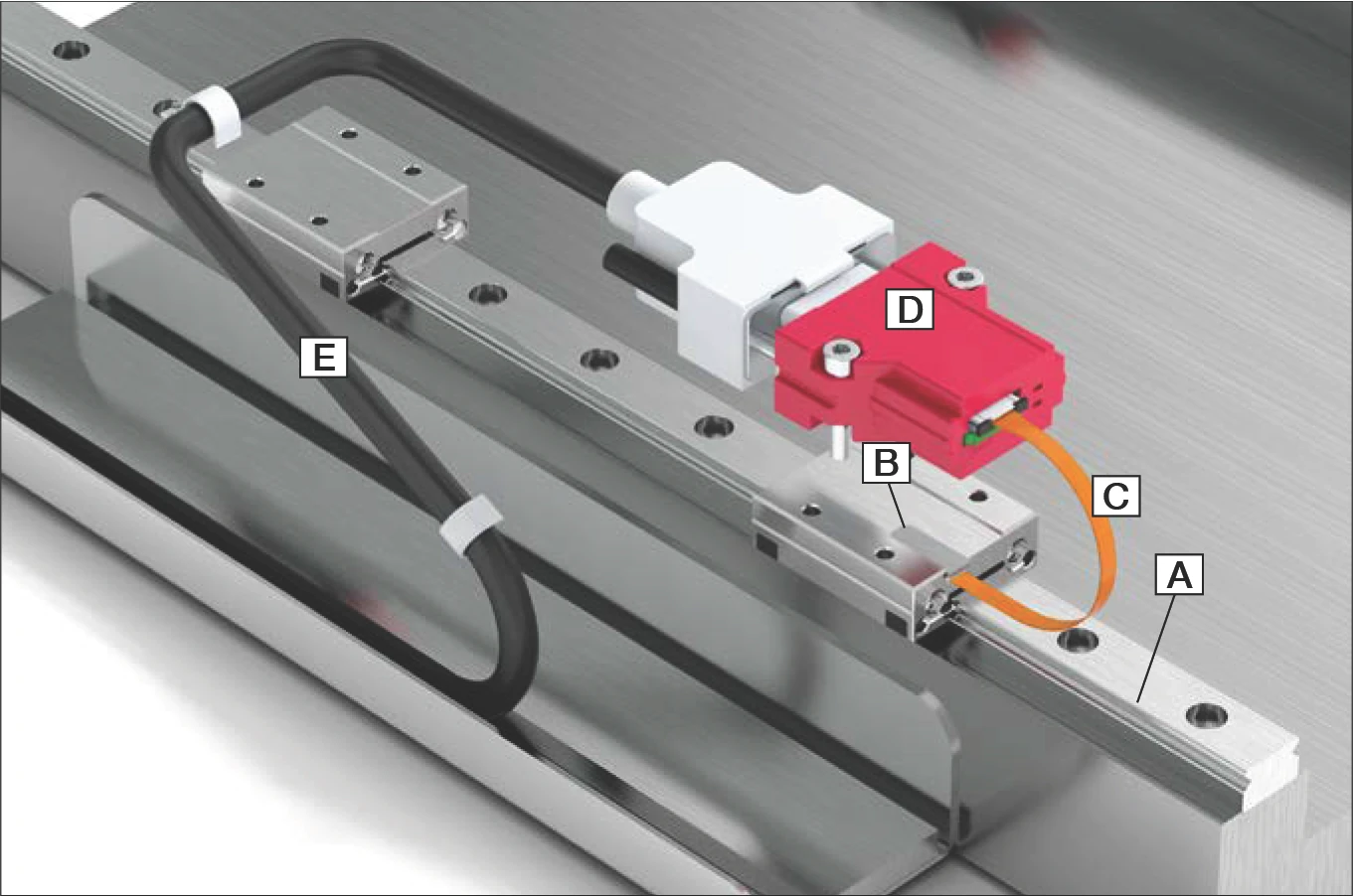
Axis with MINIRAIL, MINISCALE PLUS and interface module
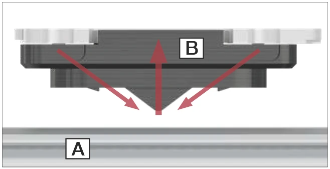
Sensor principle
A: Dimensional scale on the guideway | B: Sensor in the carriage
Dimensional scale and optical sensor
The high-precision dimensional scale is part of the hardened guideway surface, with a scale pitch of 100 µm. Two LEDs in the sensor illuminate the dimensional scale. Illuminating different structural areas produces light and dark fields. These optical signals are detected by the sensor and converted into electrical signals. The raw signals from the sensor are processed by the interface module.
The illumination level of the LEDs is actively controlled. This counteracts ageing effects of the system and compensates for contamination on the dimensional scale.
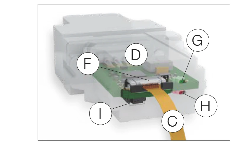
MINISCALE PLUS sensor components
Components of the interface module
Interface module
The raw signals are processed by the interface module and converted into standard output signals. Analog or digital interface modules are available.
Ensure that the ZIF connector F is easily accessible and that the LED indicators (G and H) on the interface module are clearly visible. Unlike the analog interface, the digital interface includes a compensation button I, which must also be easily accessible.
- C Flexible sensor printed circuit
- D Electronics (available in various construction types)
- F ZIF connector
- G Green LED (operating voltage indicator)
- H Red LED (error indicator)
- I Compensation button (digital interface module only)
The following construction types of the interface module are available:
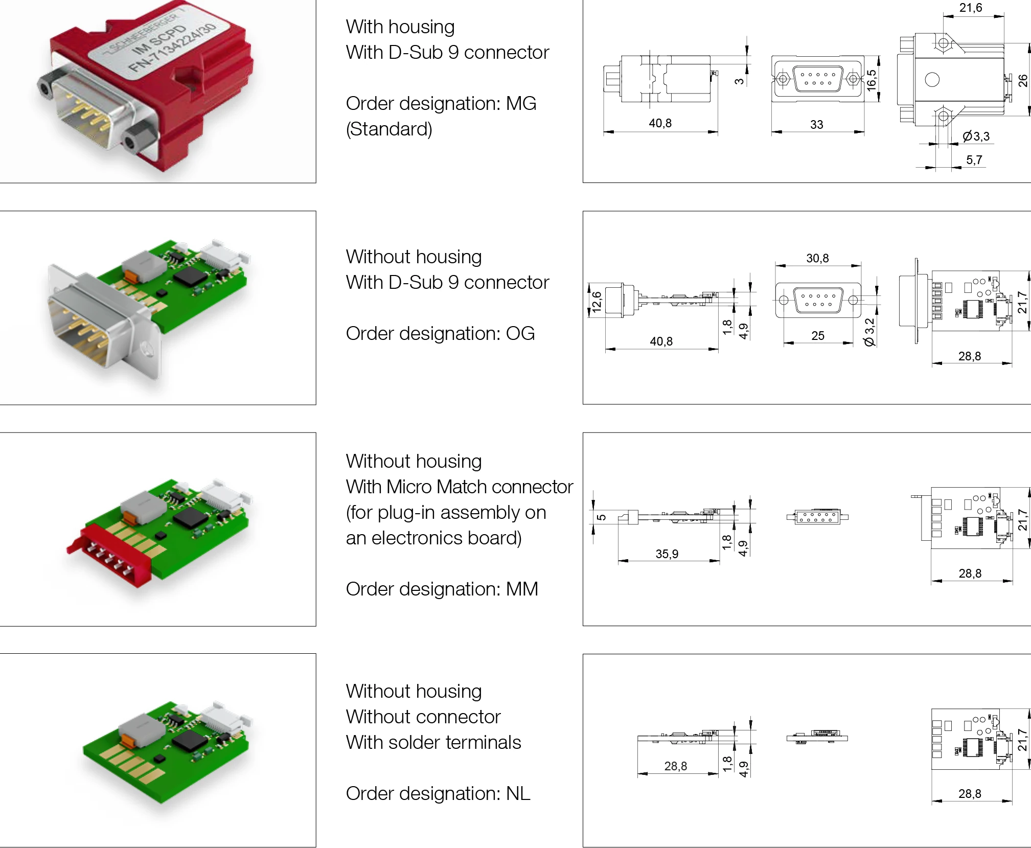
Construction types of the interface module
For customers with electronics expertise, digital interface modules can also be assembled and integrated into the customer's own electronics after consultation with SCHNEEBERGER.
Order code: KI
10.2.5 Signal Processing
Further information on signal processing is available in the download area of our website:www.schneeberger.com
Analog output format
Differential sin/cos analog signals with reference pulse, 1 Vpp (at 120 Ω).
The incremental signals sine and cosine are 90° out of phase and correlated with the markings on the encoder scale. One electrical signal period (360°) corresponds precisely to the scale pitch of the dimensional scale, 100 µm.
The reference pulse always marks the same section of the sine and cosine signal paths electronically. Therefore, the intersection of the two signals within the reference pulse marks a precisely defined position on the dimensional scale.
The sine signal either lags behind the cosine signal or appears before it, depending on the direction of motion.
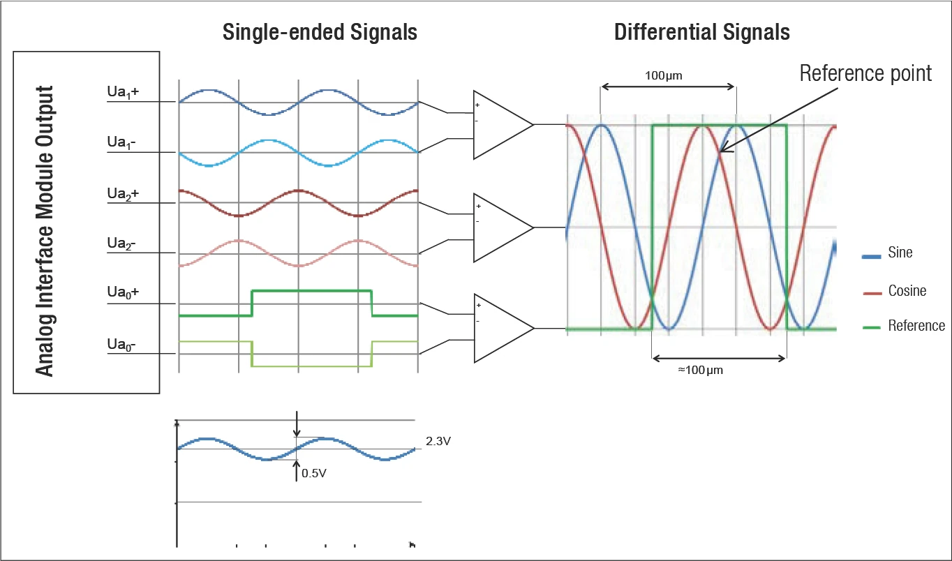
Differential signals output by the analog interface module
Single-ended signals | Differential signals (sine, cosine, reference)
Digital output format
Differential interpolated digital signals with reference pulse (A, B, R) TTL signals (RS422).
The digital interface module both processes the raw signals and interpolates the processed analog signals. Interpolation achieves a resolution of 100 nm.
The digital signal waveform consists of A and B signals. The spacing between the two edges of signals A and B corresponds precisely to a distance of 100 nm. Thus the 100 µm pitch of the encoder scale is divided by interpolation into 1000 segments of 100 nm. The A signal either lags behind the B signal or appears before it, depending on the direction of motion.
The width of the reference pulse is the same as the spacing between the two signal edges of A and B (100 nm).
The edges of the incremental signal and the reference signal are synchronised.
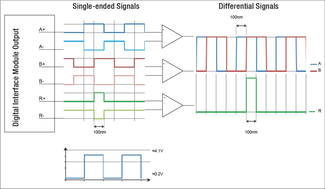
Differential signals output by the digital interface module
Single-ended signals | Differential signals (A, B, R)
10.2.6 Incremental Track
In the standard version, the incremental track extends over the entire length of the guideway. Position and length can be adapted to customer requirements.
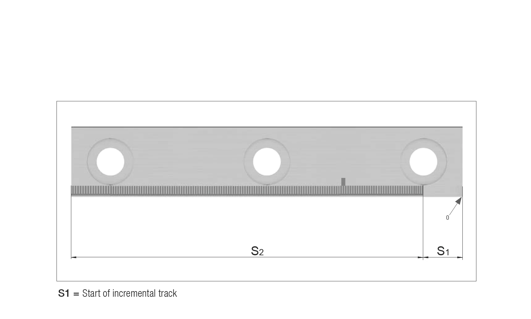
Position and length of the incremental track
S1 = start of incremental track | S2 = length of incremental track
S1 = Start of the incremental track
S2 = Length of the incremental track
Restrictions
- For analog MINISCALE PLUS guideways, S2 must be at least 30 mm.
Reference marks
Incremental measuring systems cannot determine the exact position when switched on. For this reason the reference track is added alongside the incremental track. One or multiple reference points can be marked on the reference track.
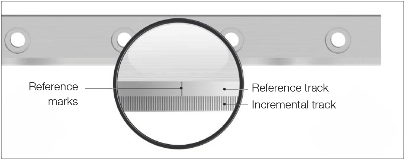
MINISCALE PLUS guideway with dimensional scale
Reference track | Incremental track | Reference marks
Standard version
The following reference position is defined as standard for all sizes:
- Referencing in the centre of the first and second fixing hole
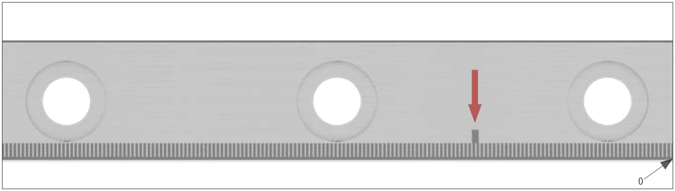
Standard position of the reference marks for all sizes
Special versions
Any number of reference marks can be chosen at any position along the reference track. It is necessary for the reference marks to be synchronised with the dimensional scale. Specifically this means that the reference marks can only be placed in multiples of 0.1 mm, since the pitch of the dimensional scale is 0.1 mm. A minimum distance of 1.5 mm between the reference marks should be maintained. Additionally, the distance between the end of the incremental track and the reference mark must be at least 2 mm.
Restrictions
- The attachment holes on guideways of type 7 and 9 are located on the reference track. The reference marks must therefore be placed BETWEEN the attachment holes for both of these sizes.
- When specifying the reference mark(s), ensure they can be seen by the carriage's sensor.
10.2.7 Analog (1VSS) and Digital (TTL) Interface Module Pin Connections
MINISCALE PLUS provides 9-pin D-Sub male connector or solder terminals as interface connection options.
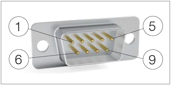
D-Sub 9 connector pin connections on the interface module
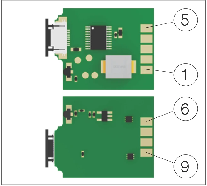
Interface module solder terminal connections
9-pin D-Sub male connector or solder terminals:
| Pin | Analog signal | Digital signal | Description |
|---|---|---|---|
| 1 | Ua1- | A - | Quadrature signal |
| 2 | 0V | 0V | Ground |
| 3 | Ua2- | B - | Quadrature signal |
| 4 | ERR NOT | ERR NOT | Error signal (low = error) |
| 5 | Ua0 - | R - | Reference signal |
| 6 | Ua1 + | A + | Quadrature signal |
| 7 | + 5V DC | + 5V DC | Supply voltage |
| 8 | Ua2 + | B + | Quadrature signal |
| 9 | Ua0 + | R + | Reference signal |
10-pin ZIF connector:
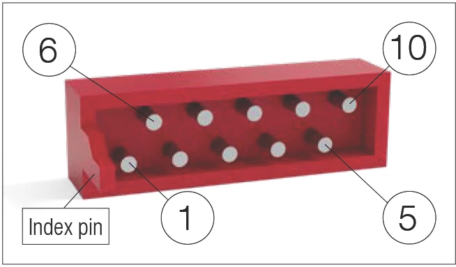
ZIF connector pin configuration on the interface module
| Pin | Analog signal | Digital signal | Description |
|---|---|---|---|
| 1 | nc | nc | Not connected |
| 2 | Ua1 + | A + | Quadrature signal |
| 3 | + 5V DC | + 5V DC | Supply voltage |
| 4 | Ua2 + | B + | Quadrature signal |
| 5 | Ua0 + | R + | Reference signal |
| 6 | Ua1 - | A - | Quadrature signal |
| 7 | 0V | 0V | Ground |
| 8 | Ua2 - | B - | Quadrature signal |
| 9 | ERR NOT | ERR NOT | Error signal (low = error) |
| 10 | Ua0 - | R - | Reference signal |
Note: Different construction types of the interface module may use different connector types. Please confirm the required connector type (D-Sub 9, ZIF, Micro Match, or solder terminal) when ordering.
10.2.8 Extensions
Extensions can be used when the interface module cannot be mounted directly on the sensor. A Flat Flex Cable (FFC) is used between the sensor printed circuit and the interface module.
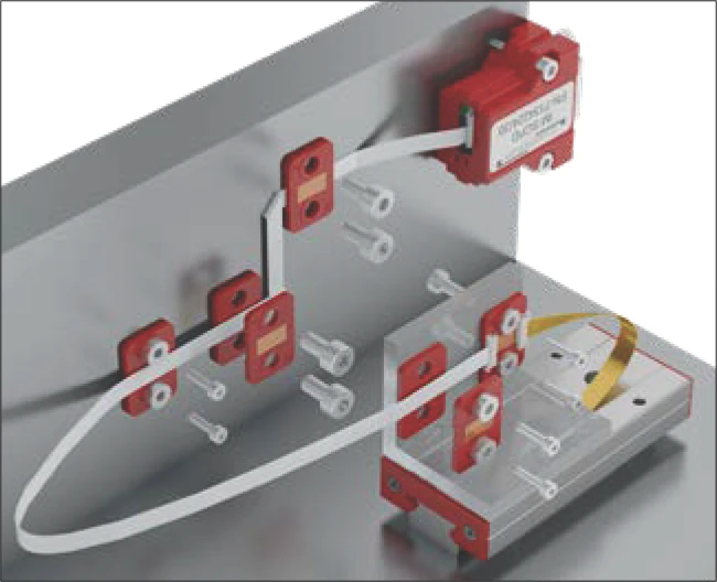
FFC extension installation example

FFC cable with adapter
Advantages of extensions:
- By relocating the interface module to a non-moving position, the mass of the moving system can be reduced.
- The shielded FFC cable supplied with the extensions is also designed for dynamic loads. The recommended minimum bending radius is 10 mm. In contrast, the flexible sensor printed circuit can only be installed statically.
- FFC cables provide low push force. This can be an advantage where cables used in cable chains are too rigid.
- The FFC cable can also be folded once during installation.
FFC cables are available in three lengths: 250 mm, 400 mm and 600 mm. The extension cables are supplied with adapter plates.
Adapter
Used for the electrical connection between the sensor printed circuit and the extension cable. Two ZIF connectors are provided on the adapter for this purpose.
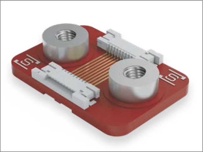
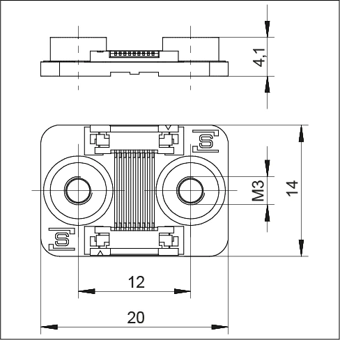
Adapter - 20×14 mm, M3 threaded holes
Clamp Plate
Can be used for strain relief or to guide the FFC cable. Two M3 spacers are mounted on the plate.
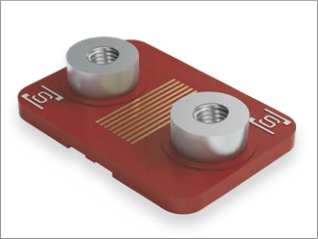
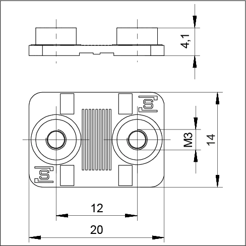
Clamp Plate - can be used for strain relief or to guide the FFC cable
Base Plate
Can be used as a base or to clamp cables.
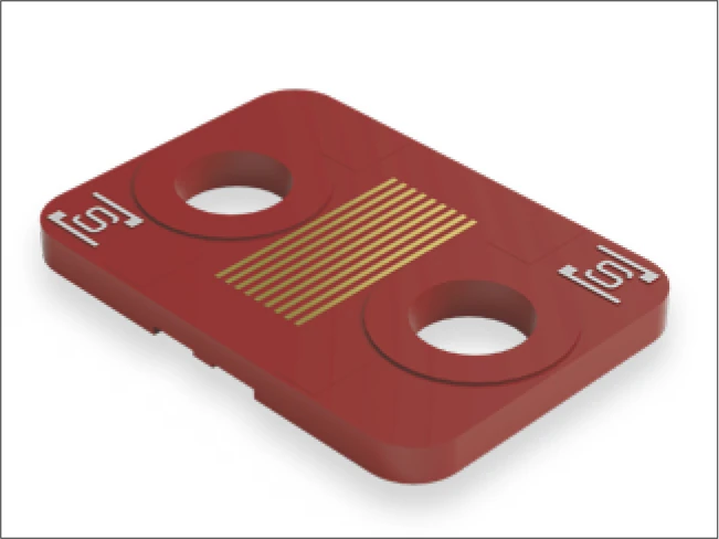
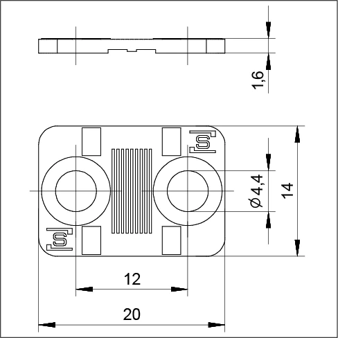
Base Plate - can be used as a base or to clamp cables
10.2.9 Lubrication
Overview
Lubrication is a design element and must therefore be defined during the development phase of a machine or application. If lubrication is specified only after the design and construction are complete, operational difficulties are likely. A carefully designed lubrication concept is therefore a hallmark of advanced and thoughtful design.
Parameters to consider when choosing a lubricant:
| Operating conditions | Speed, acceleration, stroke, load, installation orientation |
|---|---|
| External influences | Temperature, corrosive media or radiation, contamination, humidity, vacuum, clean room |
| Relubrication | Time interval, quantity, compatibility |
| Compatibility | Compatibility with other lubricants, with corrosion protection, and with integrated materials (e.g. plastics) |
Important: Proper lubrication is essential for reliable long-term operation of MINISCALE PLUS. Please select a lubricant according to your specific application conditions and observe the recommended relubrication intervals.