12.1 Dimensions of accessories
Dimensions of MRK/BRK plastic plugs
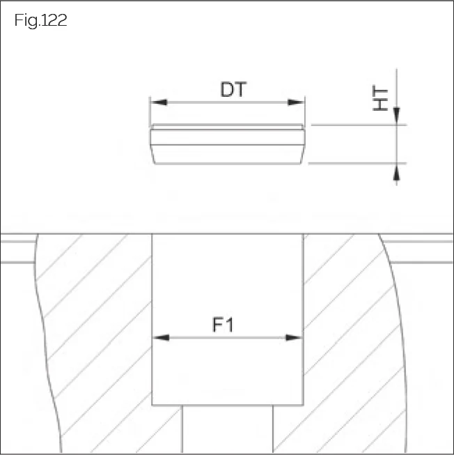
Fig.122
| Size | ØDT | HT | F1 |
|---|---|---|---|
| MRK 25 | 11.4 | 1.2 | 11 |
| MRK 30/35 | 15.3 | 3.9 | 15 |
| MRK 45 | 20.3 | 4.5 | 20 |
| MRK 55 | 24.3 | 5.7 | 24 |
| MRK 65 | 26.4 | 6 | 26 |
| MRK 100 | 39.4 | 6 | 39 |
| Size | ØDT | HT | F1 |
|---|---|---|---|
| BRK 15 | 8.2 | 2.1 | 8 |
| BRK 20 | 10.3 | 2.6 | 10 |
| BRK 25 | 11.3 | 2.7 | 11 |
| BRK 30/35 | 15.3 | 5.0 | 15 |
| BRK 45 | 20.3 | 4.7 | 20 |
All dimensions in mm
Dimensions of MRS/BRS brass plugs
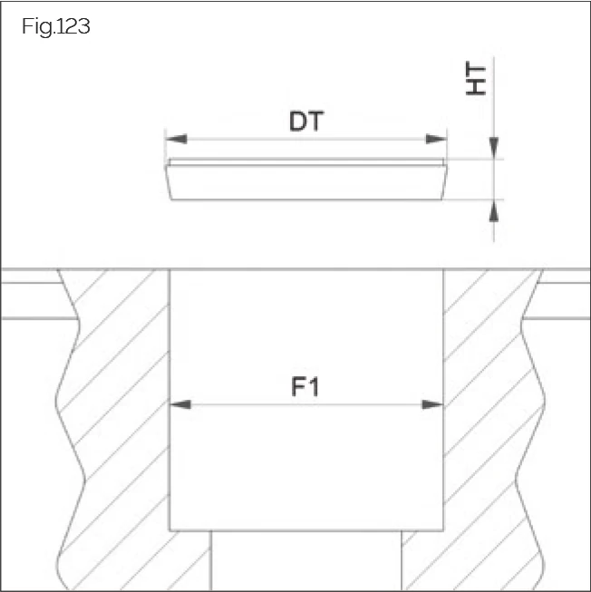
Fig.123
| Size | ØDT | HT | F1 |
|---|---|---|---|
| MRS 25 | 11.5 | 2.5 | 11 |
| MRS 30/35 | 15.5 | 3 | 15 |
| MRS 45 | 20.5 | 3 | 20 |
| MRS 55 | 24.5 | 3 | 24 |
| MRS 65 | 26.5 | 3 | 26 |
| MRS 100 | 39.5 | 5 | 39 |
| Size | ØDT | HT | F1 |
|---|---|---|---|
| BRS 15 | 8.2 | 2 | 8 |
| BRS 20 | 10.2 | 2.2 | 10 |
| BRS 25 | 11.2 | 2.4 | 11 |
| BRS 30/35 | 15.1 | 3 | 15 |
| BRS 45 | 20.1 | 2.5 | 20 |
All dimensions in mm
Dimensions of MRZ steel plugs
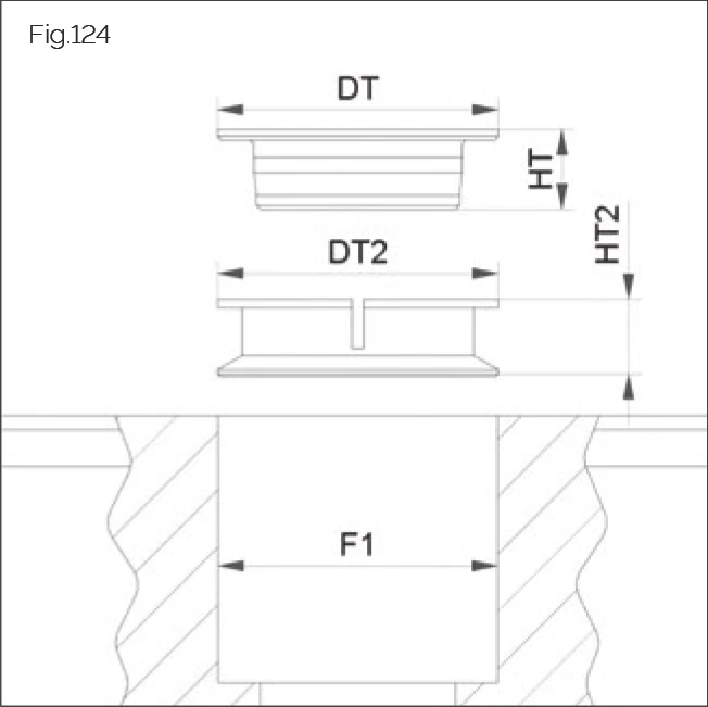
Fig.124
| Size | ØDT | HT | ØDT2 | HT2 | ØF1 |
|---|---|---|---|---|---|
| MRZ 25 | 11 | 4.3 | 11 | 4.5 | 11 |
| MRZ 30/35 | 15 | 8 | 15 | 7.5 | 15 |
| MRZ 45 | 20 | 5.7 | 20 | 5.5 | 20 |
| MRZ 55 | 24 | 6.8 | 24 | 6.5 | 24 |
| MRZ 65 | 26 | 7.6 | 26 | 8.5 | 26 |
| MRZ 100 | 39 | 13 | 39 | 11.5 | 39 |
All dimensions in mm
Dimensions of MAC/BAC cover strip
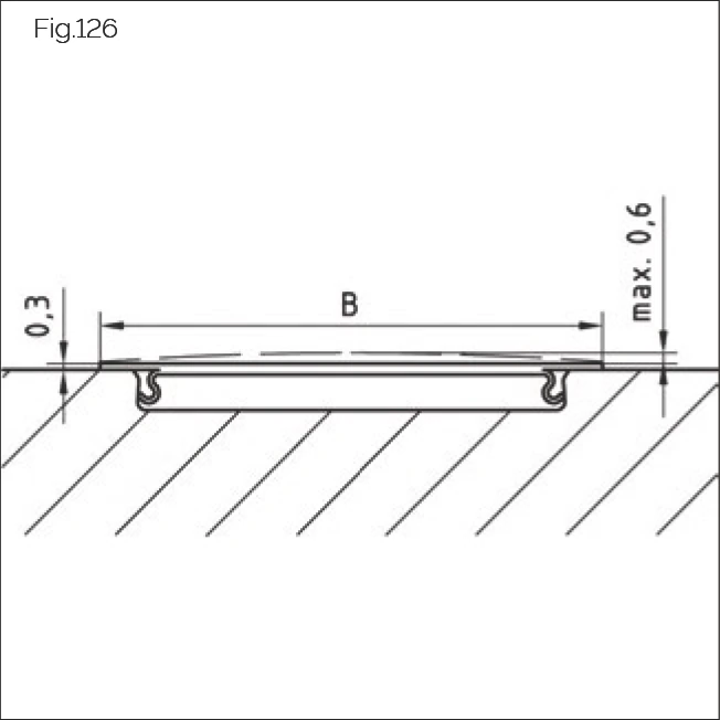
Fig.126
| Size | B |
|---|---|
| MAC 25 | 15 |
| MAC 35 | 19 |
| MAC 45 | 25 |
| MAC 55 | 28.5 |
| MAC 65 | 32 |
| Size | B |
|---|---|
| BAC 15 | 11 |
| BAC 20 | 13 |
| BAC 25 | 15 |
| BAC 30 | 19 |
| BAC 35 | 19 |
| BAC 45 | 25 |
All dimensions in mm
Dimensions of steel securing bands (BSC)
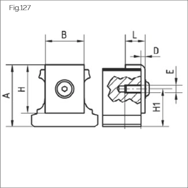
Fig.127
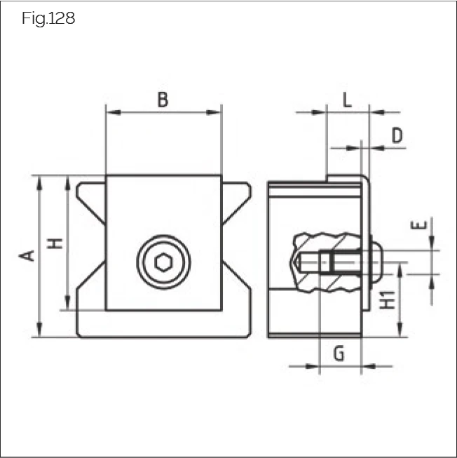
Fig.128
Steel securing bands BM version dimensions
| Size | BM | A | B | H | L | D | E | G | H1 |
|---|---|---|---|---|---|---|---|---|---|
| BSC 15 | BM 15 | 18.2 | 11 | 15 | 7 | 2 | M3 | 8.5 | 8.7 |
| BSC 20 | BM 20 | 21.5 | 13 | 20 | 8 | 2 | M3 | 8.5 | 11 |
| BSC 25 | BM 25 | 25.2 | 15 | 24 | 10 | 2 | M4 | 9 | 12.7 |
| BSC 30 | BM 30 | 28.5 | 20 | 25 | 10 | 2 | M4 | 9 | 16 |
| BSC 35 | BM 35 | 32 | 20 | 25 | 10 | 2 | M4 | 9 | 19.5 |
| BSC 45 | BM 45 | 39.5 | 30 | 35 | 11 | 2 | M6 | 11 | 17 |
Steel securing bands MR version dimensions
| Size | MR | A | B | H | L | D | E | G | H1 |
|---|---|---|---|---|---|---|---|---|---|
| BSC 25 | MR 25 | 27 | 15 | 24 | 10 | 2 | M4 | 9 | 14.5 |
| BSC 30 | MR 30 | 28.5 | 20 | 25 | 10 | 2 | M4 | 9 | 16 |
| BSC 35 | MR 35 | 34.5 | 20 | 25 | 10 | 2 | M4 | 9 | 22 |
| BSC 45 | MR 45 | 42.5 | 30 | 35 | 11 | 2 | M6 | 11 | 20 |
| BSC 55 | MR 55 | 50.5 | 30 | 35 | 11 | 2 | M6 | 11 | 28 |
| BSC 65 | MR 65 | 60.5 | 30 | 35 | 11 | 2 | M6 | 11 | 38 |
All dimensions in mm
12.2 Screw tightening torques
Tightening torques for guideways and carriages
DANGER!
Risk to life posed by falling machine elements!
If the strength of the screw connection is not sufficient to securely fasten the guideway or carriage, they may fall down.
- Profiled driven guideways should be secured using all available mounting holes and screws.
- In the case of high loads, employ constructive measures to prevent guideways or carriages from falling should the base fail.
- The recommendations of the screw suppliers must be followed.
- Ensure that the material strength of the connecting structure is sufficient.
DANGER!
Risk to life posed by falling machine elements!
The friction coefficient μ can be reduced by up to "half" when greases are used and screws can fail during tightening. The torques must be reduced accordingly.
Lubrication of the fastening screws with grease and tightening using a torque wrench enables a more even preload force to be achieved. This results in a marked improvement of running accuracy.
Maximum tightening torque (Nm)
| Screw | M4 | M5 | M6 | M8 | M10 | M12 | M14 | M16 | M20 | M24 |
|---|---|---|---|---|---|---|---|---|---|---|
| Size | 15 | 15,20 | 20,25 | 25–35 | 30–45 | 45,55 | 55,65 | 65,100 | 100 | 100 |
| Strength class 8.8 | 3 | 6 | 10 | 25 | 49 | 83 | 130 | 200 | 410 | 700 |
| Strength class 12.9 | 5 | 10 | 16 | 40 | 81 | 95 | 166 | 265 | 680 | 1100 |
μK = 0.12 (coefficient of friction in head) in accordance with VDI 2230
Tightening torques for front plates and additional wipers
See the table below for maximum tightening torques for fastening screws for the front plates.
DANGER!
Risk to life posed by falling machine elements!
Screws for securing front plates are provided with threadlocker. The adhesive force of the threadlocker is reduced by repeated screwing and unscrewing, which can lead to unwanted loosening of the screw and loosening of the front plate during operation.
- Do not re-use fastening screws several times.
- Ensure that new fastening screws are used when replacing components.
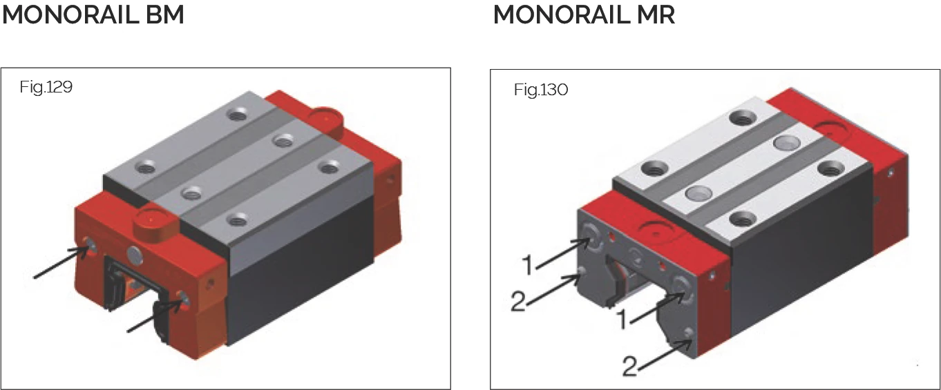
Fig.129 & Fig.130
Maximum front plate tightening torque MAnz (Nm)
MONORAIL BM
| Size | MAnz |
|---|---|
| BM 15 | 0.2 |
| BM 20 | 0.3 |
| BM 25 | 0.5 |
| BM 30 | 0.6 |
| BM 35 | 0.8 |
| BM 45 | 1 |
MONORAIL MR
| Size | MAnz Screw 1 | MAnz Screw 2 |
|---|---|---|
| MR 25 | 1.5 | 0.3 |
| MR 30 | 1.5 | 0.3 |
| MR 35 | 1.5 | 0.35 |
| MR 45 | 1.6 | 0.4 |
| MR 55 / MR 65 | 1.8 | 0.4 |
| MR 100 | 10.0 | 1.6 |
Permissible tightening torque for sealing tube connection fixing holes
- M3 set screws: 0.4 Nm
- M6 set screws: 0.8 Nm
12.3 Amount of lubricants
Scope of Application
- The lubricating volumes for MONORAIL MR are also used for AMS 3B, AMSA 3L, and AMSABS 3B.
- The lubricating volumes for MONORAIL BM also apply for AMS 4B, AMSABS 4B, and BZ.
Lubrication with grease
Initial lubrication, amount of grease per carriage (cm³)
MR carriage
| MR 25 | MR 30 | MR 35 | MR 45 | MR 55 | MR 65 | MR 100 | |
|---|---|---|---|---|---|---|---|
| A, C, E, F | 1.9 | 2.2 | 2.9 | 5.5 | 9.1 | 15.5 | 32 |
| B, D, G | 2.2 | 2.8 | 3.8 | 6.9 | 11.2 | 20.2 | 40 |
| P | - | - | - | - | - | 24.8 | - |
BM carriage
| BM 15 | BM 20 | BM 25 | BM 30 | BM 35 | BM 45 | |
|---|---|---|---|---|---|---|
| A, C, E, F, H, L | 0.9 | 1.7 | 2.8 | 4.7 | 6.6 | 12.6 |
| B, D, G | 1.6 | 2.1 | 3.5 | 5.8 | 8.1 | 15.6 |
| K, J, N, M | 0.7 | 1.4 | 1.9 | 3.3 | 4.7 | - |
NOTE: SCHNEEBERGER recommends KP2K lubricating grease in accordance with DIN 51825, or GP00N/GP000N liquid grease in accordance with DIN 51826.
- The specified lubricant volumes are valid for both grease and liquid grease.
- During greasing, move carriages three times their length several times.
- If there are two lube connections per carriage, the specified quantity should be divided accordingly.
- When using GP000N liquid grease, the installation orientation of the axis must be taken into account (separate connection).
Lubrication with oil
Initial lubrication, amount of oil per carriage (cm³)
MR carriage
| MR 25 | MR 30 | MR 35 | MR 45 | MR 55 | MR 65 | MR 100 | |
|---|---|---|---|---|---|---|---|
| Any installation position | 0.3 | 0.45 | 0.6 | 0.9 | 1.4 | 2.0 | 2.3 |
BM carriage
| BM 15 | BM 20 | BM 25 | BM 30 | BM 35 | BM 45 | |
|---|---|---|---|---|---|---|
| Any installation position | 0.2 | 0.5 | 0.6 | 0.9 | 1.1 | 1.2 |
NOTES:
- SCHNEEBERGER recommends CLP mineral oil in accordance with DIN 51517 or HLP in accordance with DIN 51524, with a viscosity range from ISO VG32 to ISO VG100 (DIN 51519).
- CGLP slideway oils can be used up to ISO VG220.
General information on lubrication
- Inject the entire oil quantity in a single impulse, or in several short impulses in quick succession, while the carriage is being moved.
- In the case of vertical installation of the carriage, the lube connection must be installed in the upper front plate.
- If there are two lube connections per carriage, the specified quantity should be divided accordingly.
- During greasing, move carriages three times their length several times.
- Take note of the installation orientation of the axis (separate connection).
- Carry out lubrication/cleaning strokes if necessary.
- Lubricate before shutdown/recommissioning.
Lubricating volumes for SPL refilling
Refilling SPL-MR (Oil quantity per 1 x SPL in cm³)
| MR 25 | MR 35 | MR 45 | MR 55 | MR 65 |
|---|---|---|---|---|
| 2.2 | 6.0 | 11.0 | 19.0 | 43.0 |
Refilling SPL-BM (Oil quantity per 1 x SPL in cm³)
| BM 15 | BM 20 | BM 25 | BM 30 | BM 35 | BM 45 |
|---|---|---|---|---|---|
| 0.5 | 1.4 | 2.4 | 2.9 | 5.8 | 10.9 |
NOTE: The SPL must be refilled using KLÜBER Lamora D 220 oil. SCHNEEBERGER GmbH Höfen/Enz assumes no liability for refilling using other lubricants.
12.4 Cable bending radii
| Cable diameter | Permissible bending radius Radius | |
|---|---|---|
| Alternative bending | Single bend | |
| 6 mm | ≥ 75 mm | ≥ 20 mm |
| 8 mm | ≥ 100 mm | ≥ 40 mm |