4.4 Cable Types Overview
SCHNEEBERGER offers various connecting cables to match different read head interfaces and control systems.
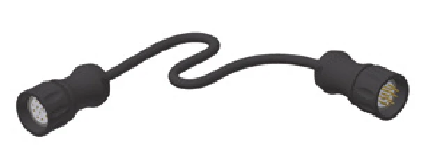
KAO 12
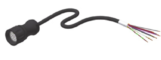
KAO 13
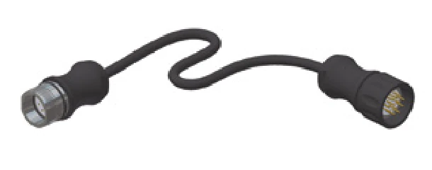
KAO 14
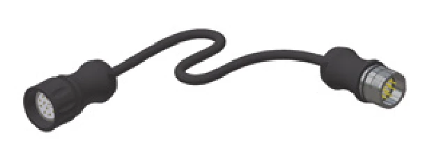
KAO 15
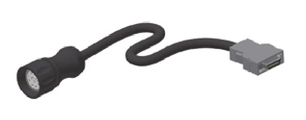
KAO 16 (FANUC)
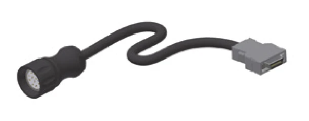
KAO 20 (FANUC)
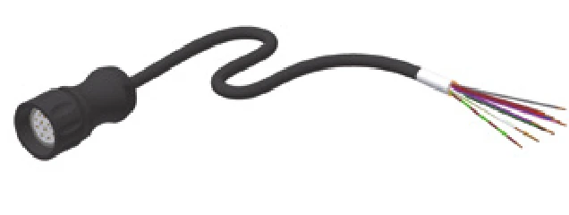
KAO 23
| Order Code | Type | Length | Compatible Read Heads |
|---|---|---|---|
| KAO 12-xx | Connecting cable, 12-core, female thread socket – female thread plug | 3, 5, 10, 15, 20m | TMU / TRU / TMD / TRD |
| KAO 13-xx | Connecting cable, 12-core, female thread socket – open ends | 3, 5, 10, 15, 20m | TMU / TRU / TMD / TRD |
| KAO 14-xx | Extension cable, 12-core, male thread socket – female thread plug | 3, 5, 10, 15, 20m | TSU / TSD |
| KAO 15-xx | Extension cable, 12-core, female thread socket – male thread plug | 3, 5, 10, 15, 20m | TMU / TRU / TMD / TRD |
| KAO 16-xx | Connecting cable, 12-core, female thread socket – FANUC plug | 3, 5, 10, 15, 20m | TMD / TRD |
| KAO 20-xx | Connecting cable, 17-core, single shielded, female thread socket – FANUC plug | 3, 5, 10, 15, 20m | TMH / TRH |
| KAO 23-xx | Connecting cable, 17-core, double shielded, female thread socket – open ends | 3, 5, 10, 15, 20m | TMH / TRH |
KAO 13 Pinout Configuration (TRU / TMU Interface)
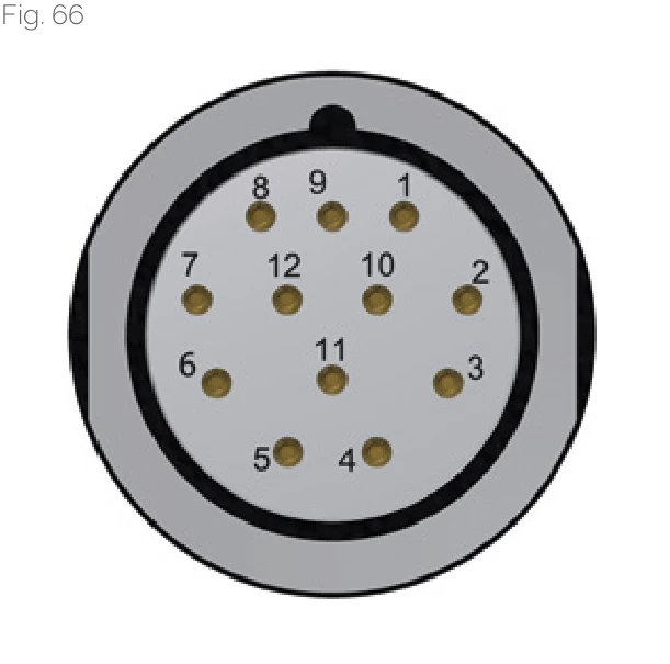
| Pin | Signal | Description | Cable Color |
|---|---|---|---|
| 1 | -Ua2 | - Cosine | pink |
| 2 | +5V Sensor | Supply voltage feed back | blue |
| 3 | +Ua0 | Reference signal | red |
| 4 | -Ua0 | Reference signal | black |
| 5 | +Ua1 | + Sine | brown |
| 6 | -Ua1 | - Sine | green |
| 7 | -Uas | NC | purple |
| 8 | +Ua2 | + Cosine | gray |
| 9 | - | NC | - |
| 10 | 0V (GND) | Supply voltage | white / green |
| 11 | 0V Sensor | Supply voltage feed back | white |
| 12 | +5 V | Supply voltage | brown / green |
KAO 13 Pinout Configuration (TRD / TMD Interface)
| Pin | Signal | Description | Cable Color |
|---|---|---|---|
| 1 | -Ua2 | A quad B signal | pink |
| 2 | +5V Sensor | Supply voltage feed back | blue |
| 3 | +Ua0 | Reference signal synchronized | red |
| 4 | -Ua0 | Reference signal synchronized | black |
| 5 | +Ua1 | A quad B signal | brown |
| 6 | -Ua1 | A quad B signal | green |
| 7 | -Oas | Error signal active low, minimum duration 20 ms | purple |
| 8 | +Ua2 | A quad B signal | gray |
| 9 | - | NC | - |
| 10 | 0V (GND) | Supply voltage | white / green |
| 11 | 0V Sensor | Supply voltage feed back | white |
| 12 | +5 V | Supply voltage | brown / green |
KAO 23 Pinout Configuration (TRH / TMH Interface)
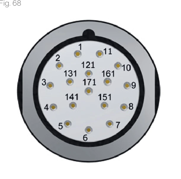
| Pin | Signal | Signal Type | Cable Color |
|---|---|---|---|
| 1 | +5V sensor | Supply voltage feedback | blue |
| 2 | - | NC | - |
| 3 | - | NC | - |
| 4 | 0V sensor | Supply voltage feedback | white |
| 5 | - | Internal parameterisation | - |
| 6 | TxD | internal parameterisation | - |
| 7 | +5V to 24V | Supply voltage | brown / green |
| 8 | +CLK | + Pulse | gray |
| 9 | -CLK | - Pulse | pink |
| 10 | 0V (GND) | Supply voltage | white / green |
| 11 | - | Inner screen | - |
| 12 | +Ua2 | + Cosine | brown |
| 13 | -Ua2 | - Cosine | green |
| 14 | +DATA | + Data | red |
| 15 | +Ua1 | + Sine | purple |
| 16 | -Ua1 | - Sine | yellow |
| 17 | -DATA | - Data | black |
Cable Installation Recommendations
Shield Connection
Cable shielding must be properly grounded to ensure signal quality and interference resistance. Grounding on the machine side is recommended.
Bend Radius
Avoid excessive cable bending. For moving applications, observe minimum bend radius requirements.
Routing Planning
Cables should be kept away from power cables and high-frequency interference sources. Use separate cable ducts when necessary.
Note
If the controller is not using the line for supply voltage feedback, lines 1 and 7 and lines 4 and 10 can be combined to reduce the voltage drop or to permit longer cable lengths. The contacts 1 and 7, and the contacts 4 and 10, are interconnected on the AMS side.