13.3 Technical Information and Alternative Variants
13.3.1 MINISLIDE MS Performance Parameters
| Max. acceleration | 50 m/s² |
|---|---|
| Max. speed | 1 m/s |
| Preload | Zero backlash |
| Accuracy | See chapters 13.3.4 and 13.3.5 |
| Materials - guideways, carriages, ball bearings | Stainless, through-hardened steel |
| Materials - cage | POM |
| Temperature range | -40 °C to +80 °C (-40 °F to +176 °F) |
| Vacuum | Vacuum (max. 10⁻⁷ mbar) |
| Humidity | 10% – 70% (non-condensing) |
| Cleanroom | Cleanroom class ISO 7 or ISO 6 (in accordance with ISO 14644-1) |
Notes:
- The standard lubrication covers a temperature range from -20 °C to +80 °C. Lubricants for other temperatures are available on request from SCHNEEBERGER (see chapter 14.2). The temperature range listed in the table above is the product hardware limit; the actual usable temperature depends on the selected lubricant.
- The suitability for a vacuum depends on the materials used. Use in a vacuum requires a special lubricant which can be requested from SCHNEEBERGER. So that no air remains trapped in the blind holes, the fastening screws must be vented.
13.3.2 MINISLIDE MSQ Performance Parameters
| Max. acceleration | 300 m/s² |
|---|---|
| Max. speed | 3 m/s |
| Preload | Zero backlash |
| Accuracy | See chapters 13.3.4 and 13.3.5 |
| Materials - guideways, carriages, ball bearings | Stainless, through-hardened steel |
| Materials - cage and pinion | PEEK |
| Materials - end pieces | PEEK |
| Temperature range | -40 °C to +150 °C (-40 °F to +302 °F) |
| Vacuum | Vacuum (max. 10⁻⁹ mbar) |
| Humidity | 10% – 70% (non-condensing) |
| Cleanroom | Cleanroom class ISO 7 or ISO 6 (in accordance with ISO 14644-1) |
Notes:
- The standard lubrication covers a temperature range from -30 °C to +120 °C. Lubricants for other temperatures are available on request from SCHNEEBERGER (see chapter 14.2). The temperature range listed in the table above is the product hardware limit; the actual usable temperature depends on the selected lubricant.
- In order to use MSQ in a vacuum, the fastening screws and the front plates must be removed. Use in a vacuum requires a special lubricant which can be requested from SCHNEEBERGER.
13.3.3 Reference and Supporting Surfaces
The locating and supporting surfaces of carriages and guideways are designated as follows.
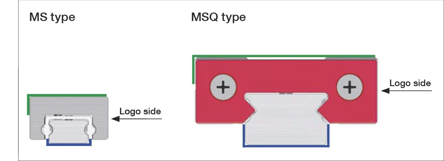
Locating surfaces of carriages and guideways for MS type and MSQ type
Note: The reference side of the carriage is opposite the carriage side with the company logo / type designation. The guideway can be located on both sides.
13.3.4 Running Accuracy and Parallelism of Supporting Surfaces
The tolerance for the straightness of the stroke depends on the length of the guideway. The following table shows the corresponding maximum values.
The measurements are taken in an unloaded state on a flat surface.
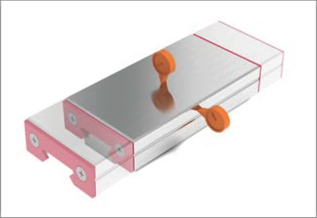
Straightness of the stroke (horizontally and vertically)
| System length L | Straightness of the stroke horizontally and vertically |
|---|---|
| 10 – 30 mm | 3 μm |
| 40 – 80 mm | 4 μm |
| 90 – 130 mm | 5 μm |
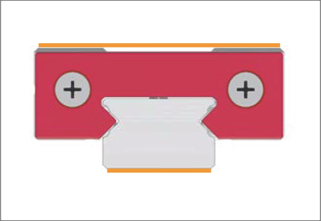
Parallelism of the supporting surfaces (frictionless table in the center position)
| System length L | Parallelism of the supporting surfaces |
|---|---|
| 10 – 30 mm | 12 μm |
| 40 – 80 mm | 15 μm |
| 90 – 130 mm | 18 μm |
13.3.5 Tolerance of the Total Height
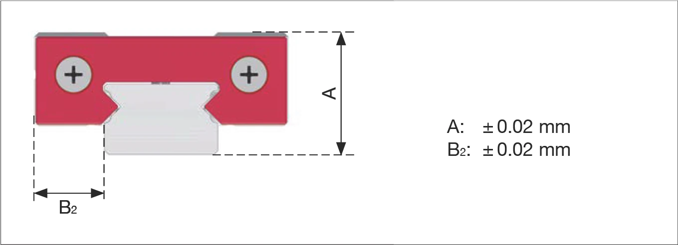
A: ± 0.02 mm, B2: ± 0.02 mm
13.3.6 Push Force and Preload
The push force is influenced by the preload and the lubricant used. MINISLIDE guideways are delivered with zero backlash and slightly preloaded as standard.
The carriages can be delivered with a defined push force on request (see chapter 14.1).
13.3.7 Friction and Smoothness
SCHNEEBERGER places high value on smoothness during manufacturing. The accuracy of the surfaces and materials is of the highest priority. This also applies with respect to the rolling elements used, which must satisfy the most stringent quality demands. Under normal operating conditions a coefficient of friction of 0.003 can be assumed.
13.3.8 Dimension Tables, Load Capacities, Weights and Moment Loads
Detailed dimension tables, load capacities, weights and moment load information for the various MINISLIDE models are provided below.
MS 4
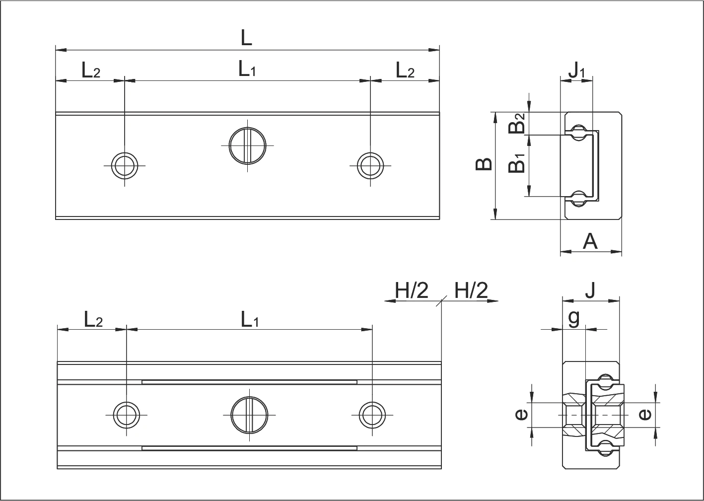
MS 4 dimension diagram
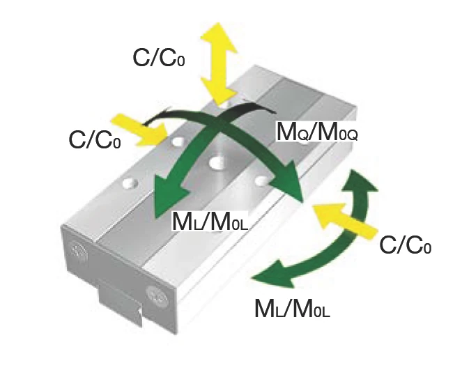
Load and torque direction diagram
| Name | MS 4-10.6 | MS 4-15.12 | MS 4-20.15 | MS 4-25.22 | |
|---|---|---|---|---|---|
| Dimensions (mm) | |||||
| A | System height | 4 | 4 | 4 | 4 |
| B | System width | 7 | 7 | 7 | 7 |
| B1 | Rail width | 4 | 4 | 4 | 4 |
| B2 | Distance between locating surfaces | 1.5 | 1.5 | 1.5 | 1.5 |
| J | Carriage height | 3.7 | 3.7 | 3.7 | 3.7 |
| J1 | Rail height | 2.1 | 2.1 | 2.1 | 2.1 |
| H | Stroke | 6 | 12 | 15 | 22 |
| L | System length | 10 | 15 | 20 | 25 |
| L1 | Attachment hole spacing | 5 | 8 | 12 | 16 |
| L2 | Attachment hole start/end spacing | 2.5 | 3.5 | 4 | 4.5 |
| e | Thread | M1.6 | M1.6 | M1.6 | M1.6 |
| g | Usable thread length | 1.5 | 1.5 | 1.5 | 1.5 |
| Ball diameter | 1 | 1 | 1 | 1 | |
| Load capacity (N) | |||||
| C₀ | Static load capacity | 277 | 347 | 485 | 555 |
| C | Dynamic load capacity (≙ C₁₀₀) | 207 | 242 | 307 | 337 |
| Torque (Nm) | |||||
| M₀Q | Permissible lateral static torque | 0.60 | 0.75 | 1.04 | 1.19 |
| M₀L | Permissible static torque lengthwise | 0.40 | 0.61 | 1.13 | 1.46 |
| MQ | Permissible lateral dynamic torque | 0.45 | 0.52 | 0.66 | 0.72 |
| ML | Permissible dynamic torque lengthwise | 0.30 | 0.42 | 0.72 | 0.88 |
| Weight (g) | |||||
| Weight | 1.7 | 2.6 | 3.4 | 4.3 | |
MS 5
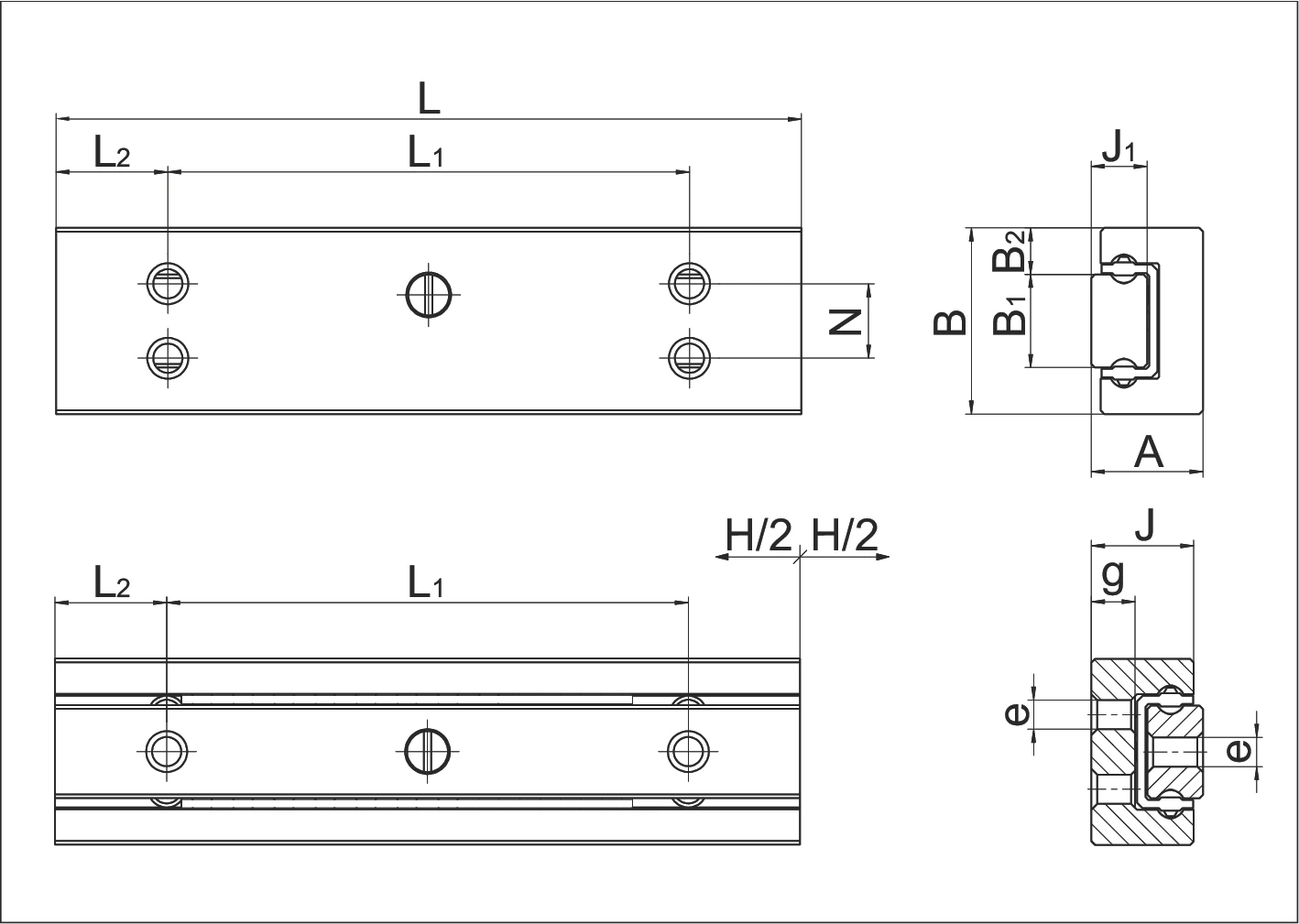
MS 5 dimension diagram
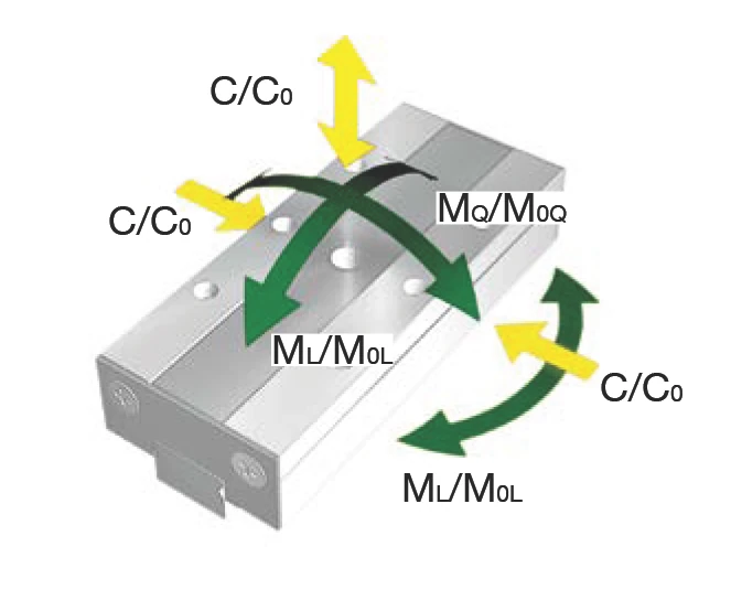
Load and torque direction diagram
| Name | MS 5-15.8 | MS 5-20.13 | MS 5-30.20 | MS 5-40.31 | MS 5-50.42 | |
|---|---|---|---|---|---|---|
| Dimensions (mm) | ||||||
| A | System height | 6 | 6 | 6 | 6 | 6 |
| B | System width | 10 | 10 | 10 | 10 | 10 |
| B1 | Rail width | 5 | 5 | 5 | 5 | 5 |
| B2 | Distance between locating surfaces | 2.5 | 2.5 | 2.5 | 2.5 | 2.5 |
| J | Carriage height | 5.5 | 5.5 | 5.5 | 5.5 | 5.5 |
| J1 | Rail height | 3 | 3 | 3 | 3 | 3 |
| H | Stroke | 8 | 13 | 20 | 31 | 42 |
| L | System length | 15 | 20 | 30 | 40 | 50 |
| L1 | Attachment hole spacing | 8 | 12 | 20 | 28 | 36 |
| L2 | Attachment hole start/end spacing | 3.5 | 4 | 5 | 6 | 7 |
| N | Lateral attachment hole spacing | 4 | 4 | 4 | 4 | 4 |
| e | Thread | M2 | M2 | M2 | M2 | M2 |
| g | Usable thread length | 2.35 | 2.35 | 2.35 | 2.35 | 2.35 |
| Ball diameter | 1.5 | 1.5 | 1.5 | 1.5 | 1.5 | |
| Load capacity (N) | ||||||
| C₀ | Static load capacity | 780 | 936 | 1404 | 1716 | 2028 |
| C | Dynamic load capacity (≙ C₁₀₀) | 568 | 645 | 857 | 987 | 1109 |
| Torque (Nm) | ||||||
| M₀Q | Permissible lateral static torque | 2.18 | 2.62 | 3.93 | 4.80 | 5.68 |
| M₀L | Permissible static torque lengthwise | 1.72 | 2.4 | 5.15 | 7.55 | 10.4 |
| MQ | Permissible lateral dynamic torque | 1.59 | 1.81 | 2.40 | 2.76 | 3.11 |
| ML | Permissible dynamic torque lengthwise | 1.25 | 1.66 | 3.14 | 4.34 | 5.69 |
| Weight (g) | ||||||
| Weight | 5.4 | 7.3 | 11 | 14.8 | 18.6 | |
MSQ 7
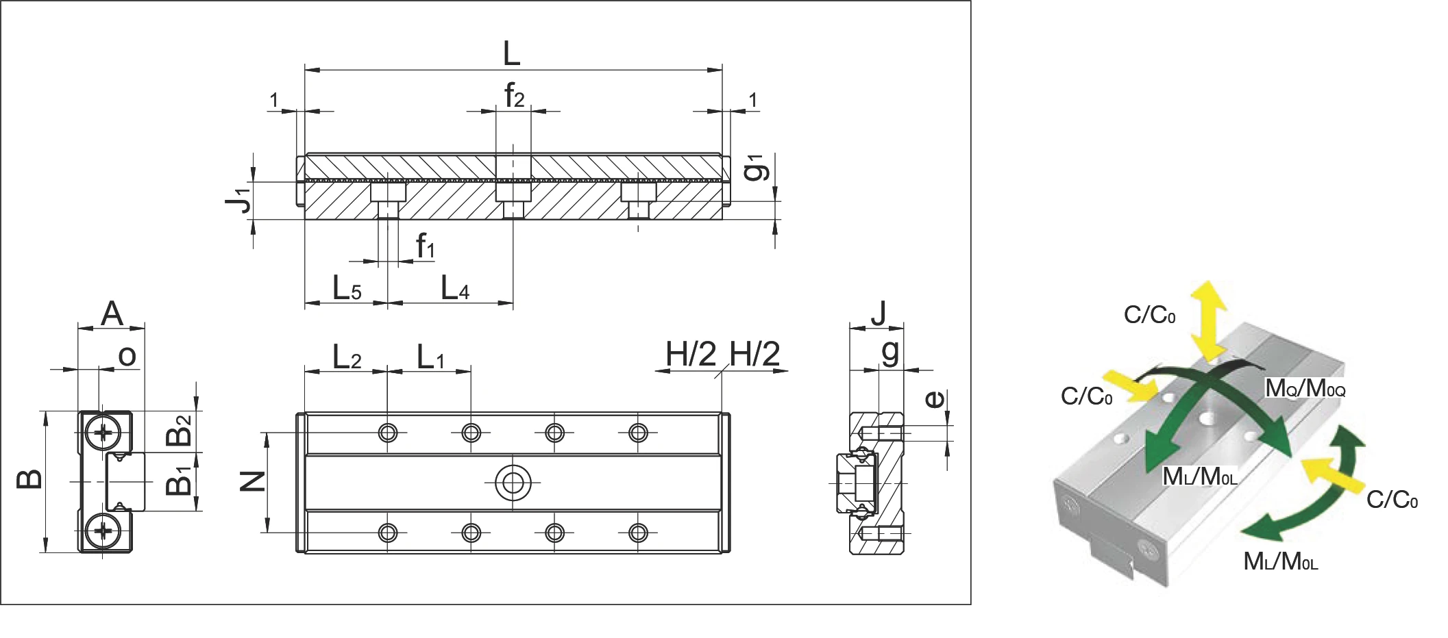
MSQ 7 dimension and load/torque direction diagram
| Name | MSQ 7-30.20 | MSQ 7-40.28 | MSQ 7-50.36 | MSQ 7-60.50 | MSQ 7-70.58 | |
|---|---|---|---|---|---|---|
| Dimensions (mm) | ||||||
| A | System height | 8 | 8 | 8 | 8 | 8 |
| B | System width | 17 | 17 | 17 | 17 | 17 |
| B1 | Rail width | 7 | 7 | 7 | 7 | 7 |
| B2 | Distance between locating surfaces | 5 | 5 | 5 | 5 | 5 |
| J | Carriage height | 6.5 | 6.5 | 6.5 | 6.5 | 6.5 |
| J1 | Rail height | 4.5 | 4.5 | 4.5 | 4.5 | 4.5 |
| H | Stroke | 20 | 28 | 36 | 50 | 58 |
| L | System length | 30 | 40 | 50 | 60 | 70 |
| L1 | Attachment hole spacing | 10 | 10 | 10 | 10 | 10 |
| L2 | Attachment hole start/end spacing | 10 | 10 | 10 | 10 | 10 |
| L4 | Attachment hole spacing | 15 | 15 | 15 | 15 | 15 |
| L5 | Attachment hole start/end spacing | 7.5 | 5 | 10 | 7.5 | 5 |
| N | Lateral attachment hole spacing | 12 | 12 | 12 | 12 | 12 |
| e | Thread | M2 | M2 | M2 | M2 | M2 |
| f1 | Attachment hole diameter | 2.4 | 2.4 | 2.4 | 2.4 | 2.4 |
| f2 | Screw hole diameter | 4.2 | 4.2 | 4.2 | 4.2 | 4.2 |
| g | Usable thread length | 3 | 3 | 3 | 3 | 3 |
| g1 | Clamping length | 2.2 | 2.2 | 2.2 | 2.2 | 2.2 |
| Ball diameter | 1 | 1 | 1 | 1 | 1 | |
| Load capacity (N) | ||||||
| C₀ | Static load capacity | 1193 | 1670 | 2148 | 2386 | 2864 |
| C | Dynamic load capacity (≙ C₁₀₀) | 609 | 770 | 919 | 989 | 1124 |
| Torque (Nm) | ||||||
| M₀Q | Permissible lateral static torque | 5.1 | 7.2 | 9.2 | 10.3 | 12.3 |
| M₀L | Permissible static torque lengthwise | 5.0 | 8.6 | 13.1 | 15.8 | 21.8 |
| MQ | Permissible lateral dynamic torque | 2.6 | 3.3 | 4.0 | 4.3 | 4.8 |
| ML | Permissible dynamic torque lengthwise | 2.5 | 4.0 | 5.6 | 6.5 | 8.5 |
| Weight (g) | ||||||
| Weight | 24.5 | 32.6 | 40.5 | 48.5 | 56.3 | |
MSQ 9
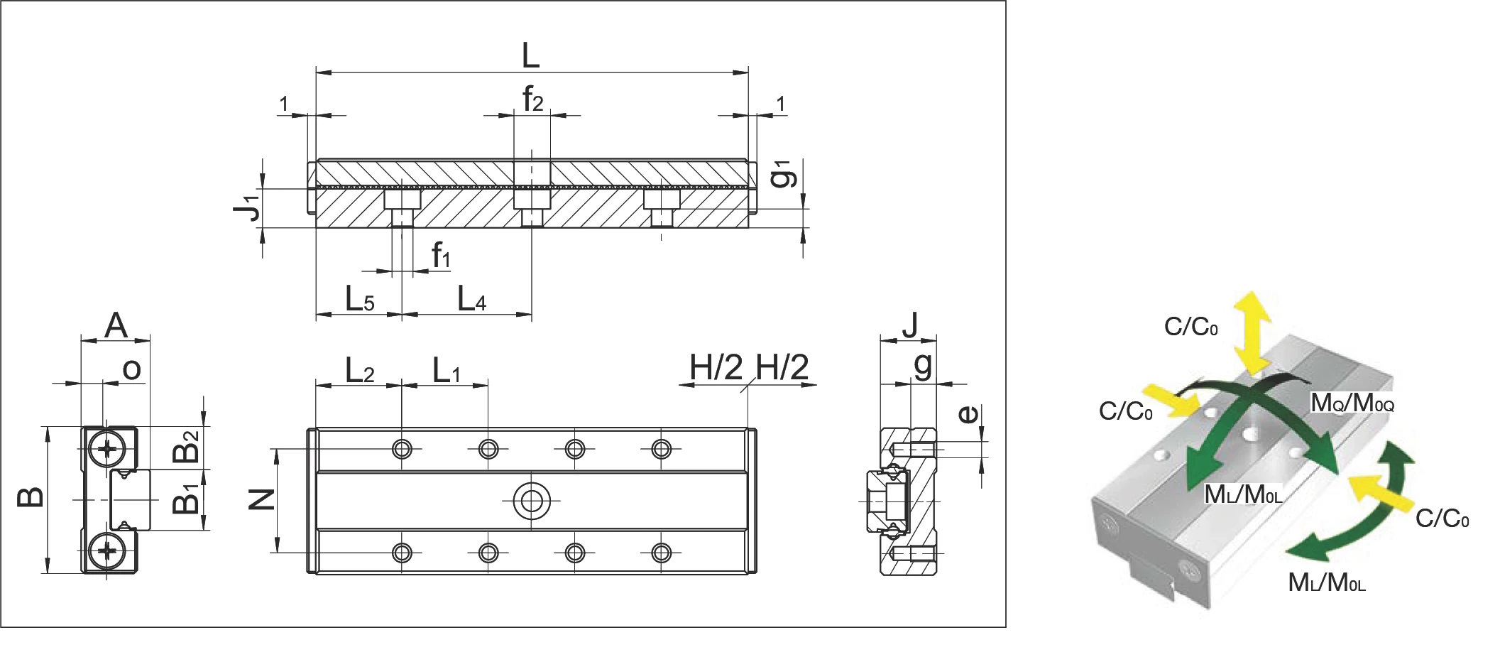
MSQ 9 dimension and load/torque direction diagram
| Name | MSQ 9-40.34 | MSQ 9-50.42 | MSQ 9-60.50 | MSQ 9-70.58 | MSQ 9-80.66 | |
|---|---|---|---|---|---|---|
| Dimensions (mm) | ||||||
| A | System height | 10 | 10 | 10 | 10 | 10 |
| B | System width | 20 | 20 | 20 | 20 | 20 |
| B1 | Rail width | 9 | 9 | 9 | 9 | 9 |
| B2 | Distance between locating surfaces | 5.5 | 5.5 | 5.5 | 5.5 | 5.5 |
| J | Carriage height | 8 | 8 | 8 | 8 | 8 |
| J1 | Rail height | 5.5 | 5.5 | 5.5 | 5.5 | 5.5 |
| H | Stroke | 34 | 42 | 50 | 58 | 66 |
| L | System length | 40 | 50 | 60 | 70 | 80 |
| L1 | Attachment hole spacing | 10 | 10 | 10 | 10 | 10 |
| L2 | Attachment hole start/end spacing | 10 | 10 | 10 | 10 | 10 |
| L4 | Attachment hole spacing | 20 | 20 | 20 | 20 | 20 |
| L5 | Attachment hole start/end spacing | 10 | 5 | 10 | 5 | 10 |
| N | Lateral attachment hole spacing | 15 | 15 | 15 | 15 | 15 |
| e | Thread | M3 | M3 | M3 | M3 | M3 |
| f1 | Attachment hole diameter | 3.5 | 3.5 | 3.5 | 3.5 | 3.5 |
| f2 | Screw hole diameter | 6 | 6 | 6 | 6 | 6 |
| g | Usable thread length | 3 | 3 | 3 | 3 | 3 |
| g1 | Clamping length | 2 | 2 | 2 | 2 | 2 |
| Ball diameter | 1 | 1 | 1 | 1 | 1 | |
| Load capacity (N) | ||||||
| C₀ | Static load capacity | 1432 | 1909 | 2386 | 2864 | 3341 |
| C | Dynamic load capacity (≙ C₁₀₀) | 692 | 846 | 989 | 1124 | 1252 |
| Torque (Nm) | ||||||
| M₀Q | Permissible lateral static torque | 7.6 | 10.1 | 12.6 | 15.2 | 17.7 |
| M₀L | Permissible static torque lengthwise | 6.7 | 10.8 | 15.8 | 21.8 | 28.7 |
| MQ | Permissible lateral dynamic torque | 3.7 | 4.5 | 5.2 | 6.0 | 6.6 |
| ML | Permissible dynamic torque lengthwise | 3.2 | 4.8 | 6.5 | 8.5 | 10.7 |
| Weight (g) | ||||||
| Weight | 45.6 | 56.9 | 68.1 | 79.2 | 90.3 | |
MSQ 12
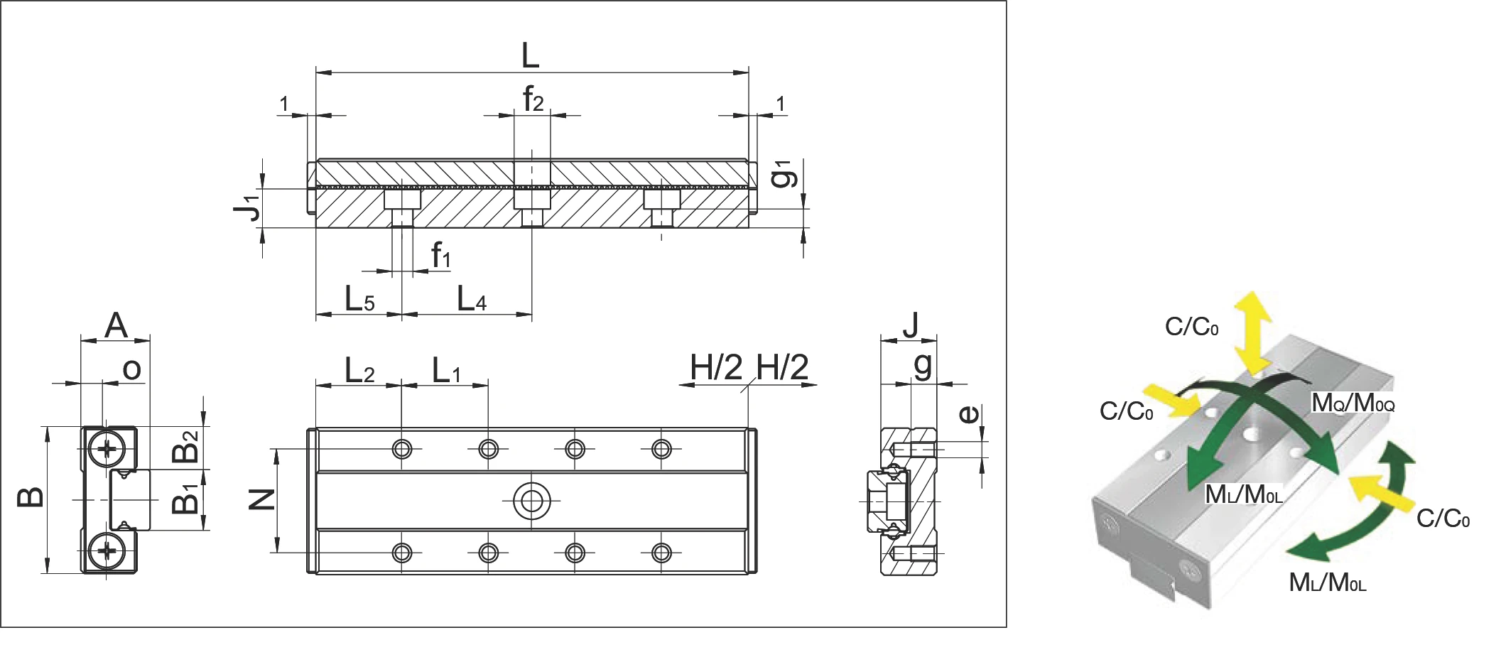
MSQ 12 dimension and load/torque direction diagram
| Name | MSQ 12-50.45 | MSQ 12-60.48 | MSQ 12-80.63 | MSQ 12-100.70 | |
|---|---|---|---|---|---|
| Dimensions (mm) | |||||
| A | System height | 13 | 13 | 13 | 13 |
| B | System width | 27 | 27 | 27 | 27 |
| B1 | Rail width | 12 | 12 | 12 | 12 |
| B2 | Distance between locating surfaces | 7.5 | 7.5 | 7.5 | 7.5 |
| J | Carriage height | 10 | 10 | 10 | 10 |
| J1 | Rail height | 7.5 | 7.5 | 7.5 | 7.5 |
| H | Stroke | 45 | 48 | 63 | 70 |
| L | System length | 50 | 60 | 80 | 100 |
| L1 | Attachment hole spacing | 15 | 15 | 15 | 15 |
| L2 | Attachment hole start/end spacing | 10 | 7.5 | 10 | 12.5 |
| L4 | Attachment hole spacing | 25 | 25 | 25 | 25 |
| L5 | Attachment hole start/end spacing | 12.5 | 5 | 15 | 12.5 |
| N | Lateral attachment hole spacing | 20 | 20 | 20 | 20 |
| e | Thread | M3 | M3 | M3 | M3 |
| f1 | Attachment hole diameter | 3.5 | 3.5 | 3.5 | 3.5 |
| f2 | Screw hole diameter | 6 | 6 | 6 | 6 |
| g | Usable thread length | 3.5 | 3.5 | 3.5 | 3.5 |
| g1 | Clamping length | 3 | 3 | 3 | 3 |
| Ball diameter | 1.5 | 1.5 | 1.5 | 1.5 | |
| Load capacity (N) | |||||
| C₀ | Static load capacity | 2685 | 3759 | 5370 | 7518 |
| C | Dynamic load capacity (≙ C₁₀₀) | 1427 | 1806 | 2318 | 2934 |
| Torque (Nm) | |||||
| M₀Q | Permissible lateral static torque | 18.9 | 26.5 | 37.9 | 53.0 |
| M₀L | Permissible static torque lengthwise | 15.7 | 27.0 | 49.5 | 90.1 |
| MQ | Permissible lateral dynamic torque | 10.1 | 12.7 | 16.3 | 20.7 |
| ML | Permissible dynamic torque lengthwise | 8.3 | 12.9 | 21.4 | 35.1 |
| Weight (g) | |||||
| Weight | 103.9 | 124.4 | 165.5 | 206.5 | |
MSQ 15
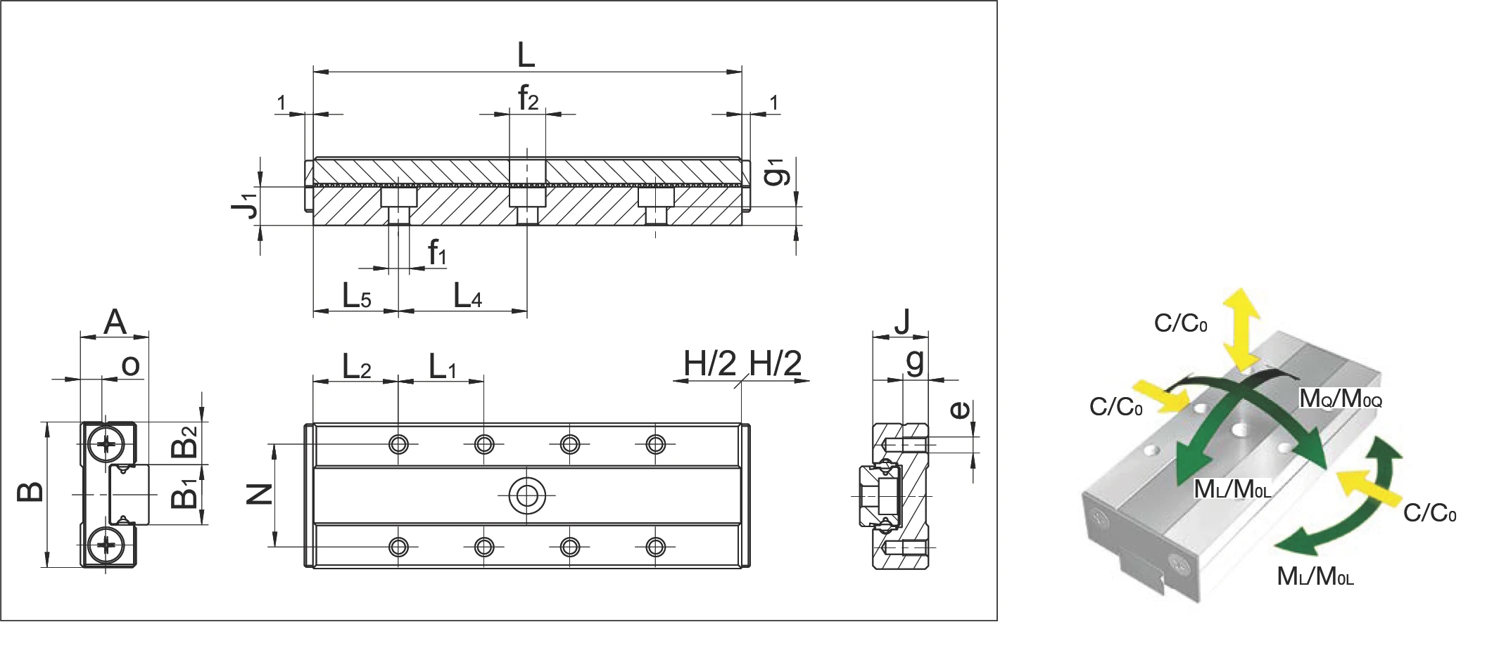
MSQ 15 dimension and load/torque direction diagram
| Name | MSQ 15-70.66 | MSQ 15-90.70 | MSQ 15-110.96 | MSQ 15-130.102 | ||
|---|---|---|---|---|---|---|
| Dimensions (mm) | ||||||
| A | System height | 16 | 16 | 16 | 16 | |
| B | System width | 32 | 32 | 32 | 32 | |
| B1 | Rail width | 15 | 15 | 15 | 15 | |
| B2 | Distance between locating surfaces | 8.5 | 8.5 | 8.5 | 8.5 | |
| J | Carriage height | 12 | 12 | 12 | 12 | |
| J1 | Rail height | 9.5 | 9.5 | 9.5 | 9.5 | |
| H | Stroke | 66 | 70 | 96 | 102 | |
| L | System length | 70 | 90 | 110 | 130 | |
| L1 | Attachment hole spacing | 20 | 20 | 20 | 20 | |
| L2 | Attachment hole start/end spacing | 15 | 15 | 15 | 15 | |
| L4 | Attachment hole spacing | 40 | 40 | 40 | 40 | |
| L5 | Attachment hole start/end spacing | 15 | 5 | 15 | 5 | |
| N | Lateral attachment hole spacing | 25 | 25 | 25 | 25 | |
| e | Thread | M3 | M3 | M3 | M3 | |
| f1 | Attachment hole diameter | 3.5 | 3.5 | 3.5 | 3.5 | |
| f2 | Screw hole diameter | 6 | 6 | 6 | 6 | |
| g | Usable thread length | 4 | 4 | 4 | 4 | |
| g1 | Clamping length | 5 | 5 | 5 | 5 | |
| Ball diameter | 2 | 2 | 2 | 2 | ||
| Load capacity (N) | ||||||
| C₀ | Static load capacity | 4773 | 7637 | 8592 | 11456 | |
| C | Dynamic load capacity (≙ C₁₀₀) | 2611 | 3628 | 3940 | 4820 | |
| Torque (Nm) | ||||||
| M₀Q | Permissible lateral static torque | 42.5 | 68 | 76.5 | 102.0 | |
| M₀L | Permissible static torque lengthwise | 36.7 | 80.9 | 99.5 | 166.6 | |
| MQ | Permissible lateral dynamic torque | 23.2 | 32.3 | 35.1 | 42.9 | |
| ML | Permissible dynamic torque lengthwise | 20.1 | 38.4 | 45.6 | 70.1 | |
| Weight (g) | ||||||
| 216.2 | 277.5 | 338.6 | 399.5 | |||
13.3.9 Lubrication
Lubrication is a design element and must therefore be defined during the development phase of a machine or application. If the lubrication is only selected after design and construction is complete, based on our experience this is likely to lead to considerable performance difficulties. A carefully thought out lubrication concept is therefore a sign of a state-of-the-art and well devised design.
Parameters to be taken into account in selecting the lubricant include:
- Operating conditions (speed, acceleration, stroke, load, installation orientation)
- External influences (temperature, aggressive media or radiation, contamination, humidity, vacuum, cleanroom)
- Subsequent lubrication (Period of time, amount)
- Compatibility (with other lubricants, with corrosion protection and with integrated materials such as plastic)
Technical and economic considerations determine the lubricant used.
MINISLIDE initial lubrication
MINISLIDE products are lubricated with Klübersynth GE 46-1200 at the factory.
MINISLIDE subsequent lubrication intervals
The lubricant should be applied to the guideway. The subsequent lubrication interval depends on different influencing variables, e.g. load, working environment, speed, etc. and can therefore not be calculated. The lubrication area should therefore be monitored over a longer period.
A) Subsequent lubrication with oil
For subsequent lubrication with oil, mineral oil CLP (DIN 51517) or HLP (DIN 51524) with a viscosity range between ISO VG32 and ISO VG150 in accordance with DIN 51519 is recommended. During lubrication, the carriages/guideways should be moved along the entire stroke length so that the lubricant is distributed correctly.
B) Subsequent lubrication with grease
For lubrication with grease, lubricating grease KP2K or KP1K is recommended in accordance with DIN 51825. During lubrication, the carriages/guideways should be moved along the entire stroke length so that the lubricant is distributed correctly.
Custom lubricants
Special lubricants are used for specific purposes. For example lubricants for use in vacuums, cleanrooms, for high or low temperatures, for high speeds or high-frequency strokes. SCHNEEBERGER can deliver the guideways with the appropriate lubricant for any of these areas of application (see chapter 14.2).