6. Installation
6.1 Fitting the first and additional gear rack(s)
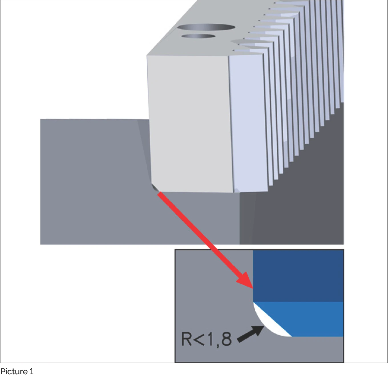
Picture 1: Chamfer between the installation and contact surfaces of the gear rack (R<1.8)
The gear rack has a chamfer between the installation and the contact surfaces (Picture 1) in order to ensure it abuts the machine bed as cleanly as possible.
The gear rack will be aligned in the best possible way if the stop bar is first of all aligned with the guide blocks. Attach the first gear rack to the machine bed, align it centrally, and then clamp it to the installation surface with the screw clamps (Picture 2).
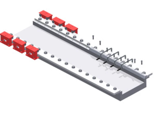
Picture 2: Clamping the first gear rack with screw clamps
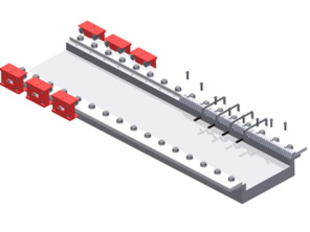
Picture 3: Placing the fixing screws
- Attach the fixing screws but do not tighten them fully
- Position the gear rack's contact surface in accordance with the guideway of the machine
- Then tighten the fixing screws with an appropriate torque from the middle outwards (see Chapter 12)
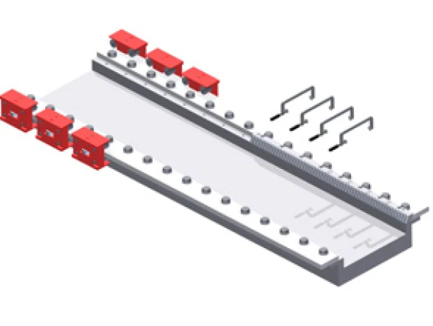
Picture 3 (cont.): Fixing screws attached
Repeat the previous steps for the remaining cylinder screws. The screw clamps can then be undone.
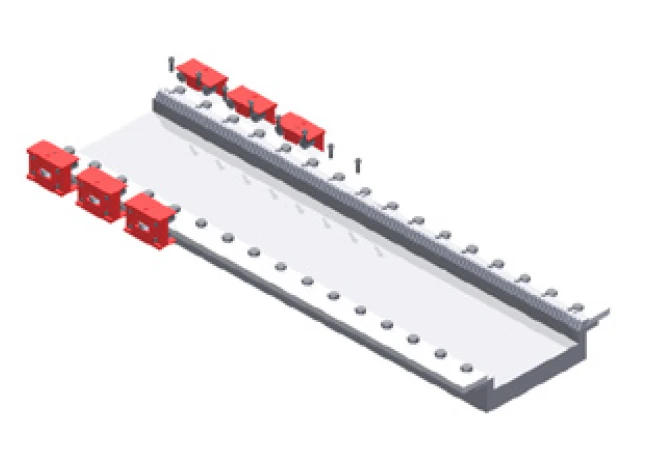
Picture 4: Fixing screws tightened, screw clamps removed
The flatness and joints of the fitted gear rack must be checked before the next gear rack is attached. Position the next gear rack over the corresponding fixing holes.
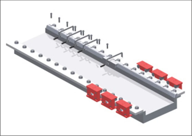
Picture 5: Fitting the next gear rack using the assembly jig (BZM)
- Attach the assembly jig (BZM) and clamp it lightly
- Clamp the gear rack to the machine bed in the area of the fixing holes
- Insert the first fixing screw in the direction of installation
- Tighten the fixing screw with an appropriate torque in the direction of installation
- Repeat the previous steps for the remaining fixing screws
- Undo all screw clamps and the assembly jig
Gear racks can be fitted in any order. However, if the gear rack is shorter than 1 metre, dowel pins are also necessary. Ensure that only gear racks with identical order codes are used for the same application.
The systems must be aligned in an axial direction over the tooth racks in such a way that the pinion does not jam when rolling over the joint. To do this, the spacing of the teeth must be set at the joint so that it corresponds with the spacing of the remaining racks and thus moves within the permissible individual pitch error of the adjacent rack.
To do this, the assembly jig (BZM) should be used for installation. This is a short rack segment with counter gearing. After the guide rails have been orthogonally aligned, they are pulled into the gearing using a clamp, and in this way the systems are axially aligned with one another. To do this, at least one of the aligned segments must be moved slightly in an axial direction.
Notes on tensioning gears
6.2 Checking the running accuracy
- Fix the dial gauge bracket onto the machine slide
- Put the measuring roller in the tooth rack on the left (A), the joint (B) and the tooth rack on the right (C), and measure the difference in height in each case with the dial gauge. The permissible height difference depends on the quality grade of the gear racks
- The joint (B) should be between the upper and lower limit of the left (A) and right (C) tooth racks
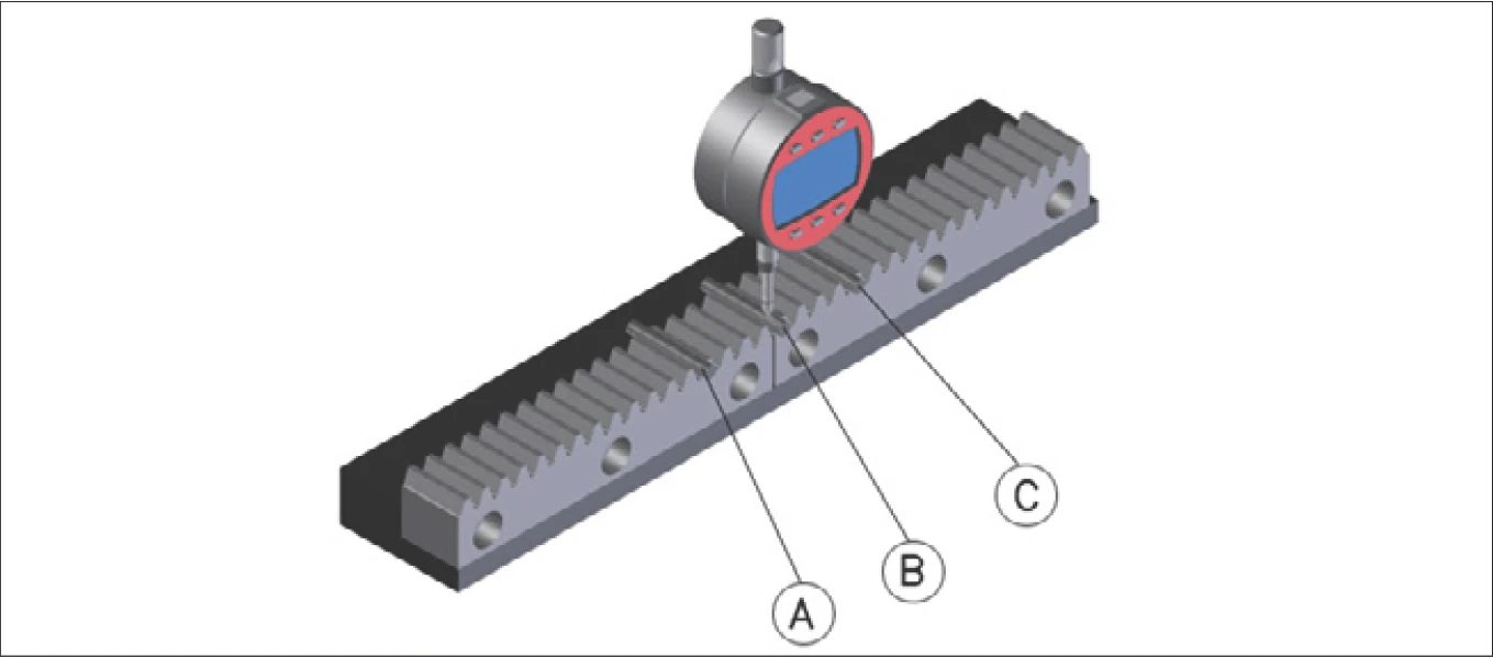
Running accuracy measurement: A = left tooth rack, B = joint, C = right tooth rack
- In the event of large deviations, use a copper tapered punch to hit the first screw hole of the previous gear rack (away from or in the direction of installation) in order to reach the height tolerance indicated on the dial gauge
- After the joint has been checked successfully, clamp the screw clamps on again, tighten them lightly once more, and tighten the cylinder screws with full torque (see Chapter 12)
- Repeat the previous steps for the other gear racks
- Remove the screw clamps
6.3 Pinning
Drill the pin holes to match the gear rack holes in the machine bed.
Ream all the holes to the correct tolerance dimension for the dowel pins (see Section 5.2).
Remove any swarf with a vacuum cleaner.
Finally, fix the gear racks with cylinder pins.
6.4 Final check
- If necessary, remove the grease from the tooth flanks of the gear rack
- Paint the tooth flanks with touch-up paint
- Move the machine table several times so that the pinion runs over the painted tooth flanks
- While doing this, check that the tooth rack moves easily
- The energy expenditure and the running noise must be the same over the whole travel distance
- There must be no impact at the joints
- Check the area where the paint was removed from the tooth flanks to assess the fit of the gear
- Assess the alignment of the gear using the contact pattern shown below
- If necessary, adjust the alignment of the gear
- Check the gear racks at the joint for pitch accuracy
Assessing alignment from the tooth flank contact pattern
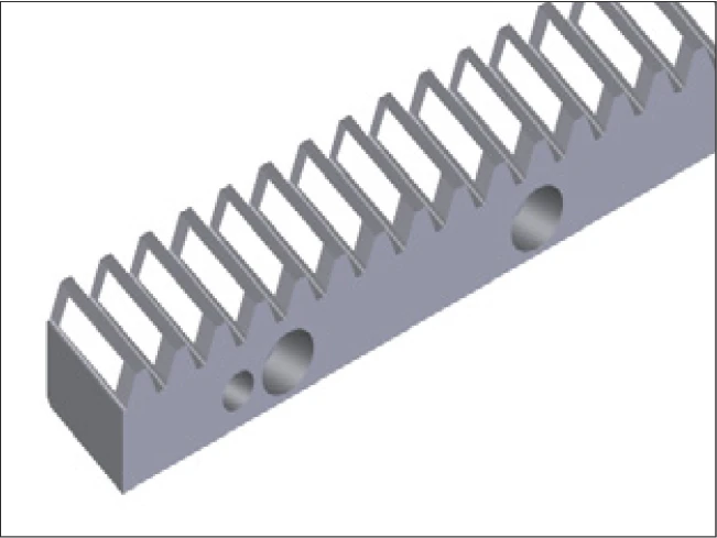
Right (straight)
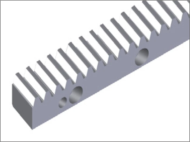
Right (helical)
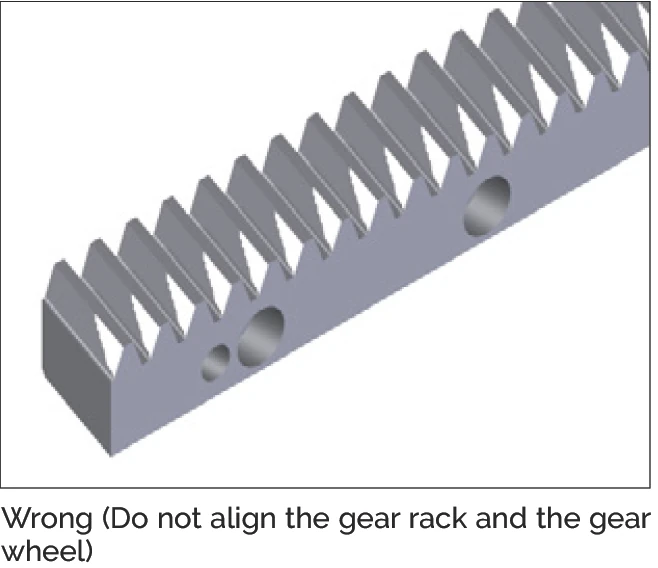
Wrong — gear rack and gear wheel not aligned
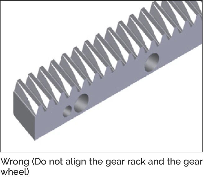
Wrong — gear rack and gear wheel not aligned