Overview: RDDS1 Matrix
The rotary direct drive systems are predestinated for high precise and high dynamic positioning tasks in the ranges of handling, productronics and automation.
RDDS1 Dimension Matrix
The table below lists four outer diameters (130 / 160 / 180 / 230 mm) and the available heights H [mm] for each diameter.
| Series | RDDS1-130xH | RDDS1-160xH | RDDS1-180xH | RDDS1-230xH |
|---|---|---|---|---|
| Diameter | 130 mm | 160 mm | 180 mm | 230 mm |
| Available Height H [mm] | ||||
| 110 | 120 | 110 | 115 | |
| 135 | 145 | 137.5 | 140 | |
| 160 | 170 | 165 | 165 | |
| 185 | 195 | 192.5 | 190 |
Abbreviation
RDDS: Rotary Direct Drive System
Overview: Peak and Continuous Torques (Not Cooled)
The table below lists the peak torque Tp (Nm) and continuous torque (not cooled) Tc (Nm) for each series at different heights. Green shading (■) indicates peak torque Tp; grey shading (■) indicates continuous torque (not cooled) Tc.
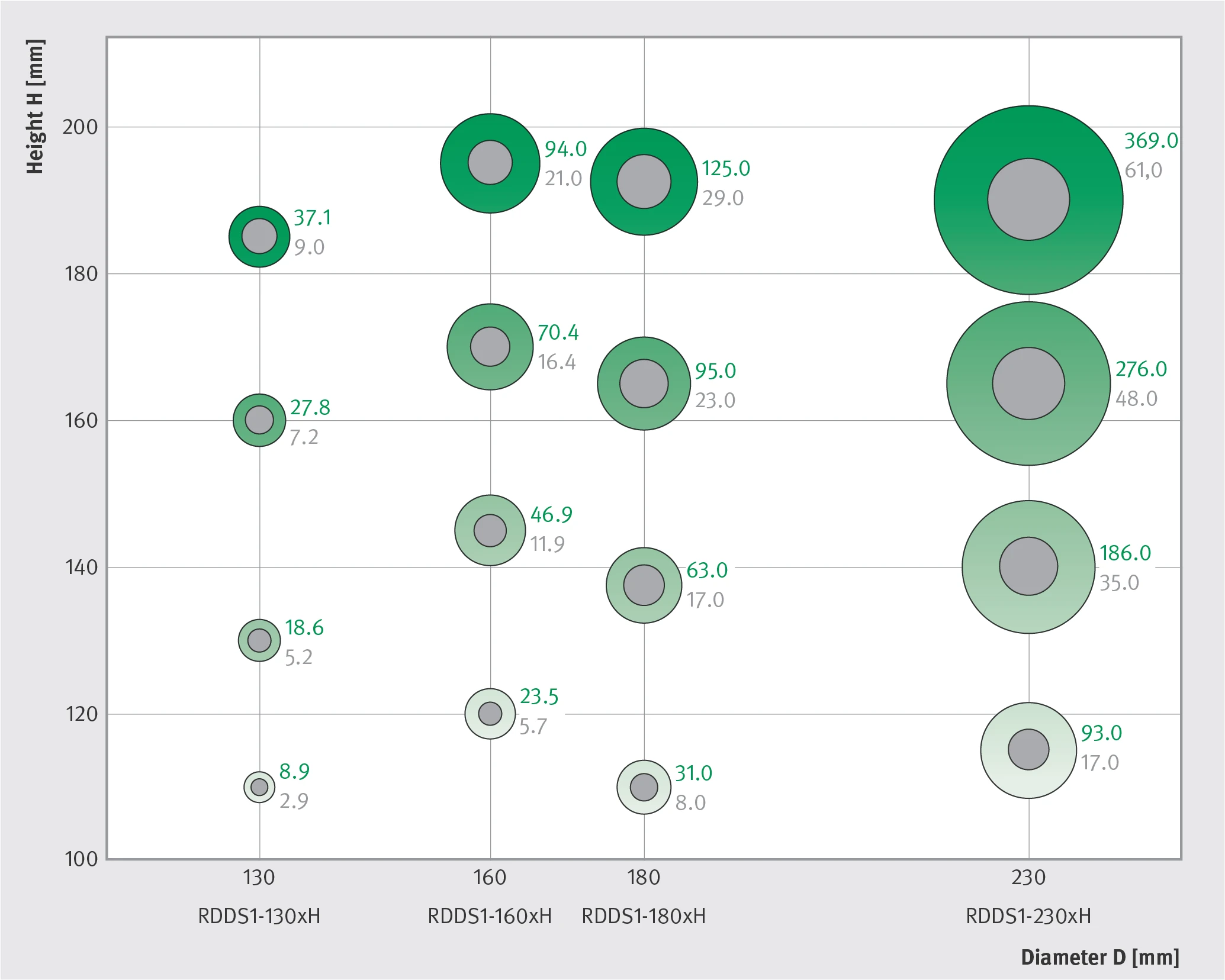
RDDS1 peak torque Tp (green) and continuous torque Tc (grey) matrix (Diameter D vs. Height H)
| Height H [mm] | Diameter 130 mm RDDS1-130xH | Diameter 160 mm RDDS1-160xH | Diameter 180 mm RDDS1-180xH | Diameter 230 mm RDDS1-230xH | ||||
|---|---|---|---|---|---|---|---|---|
| Tp [Nm] | Tc [Nm] | Tp [Nm] | Tc [Nm] | Tp [Nm] | Tc [Nm] | Tp [Nm] | Tc [Nm] | |
| 110 / 120 / 110 / 115 | 8.9 | 2.9 | 23.5 | 5.7 | 31.0 | 8.0 | 93.0 | 17.0 |
| 135 / 145 / 137.5 / 140 | 18.6 | 5.2 | 46.9 | 11.9 | 63.0 | 17.0 | 186.0 | 35.0 |
| 160 / 170 / 165 / 165 | 27.8 | 7.2 | 70.4 | 16.4 | 95.0 | 23.0 | 276.0 | 48.0 |
| 185 / 195 / 192.5 / 190 | 37.1 | 9.0 | 94.0 | 21.0 | 125.0 | 29.0 | 369.0 | 61.0 |
Height column format: minimum to maximum height for each diameter (130 mm / 160 mm / 180 mm / 230 mm), listed in order.
Legend
Green: peak torques Tp [Nm]
Grey: continuous torques (not cooled) Tc [Nm]
If you need higher continuous torques (not cooled) Tc, please do not hesitate to contact us.
Torque-Rotary Speed Characteristic
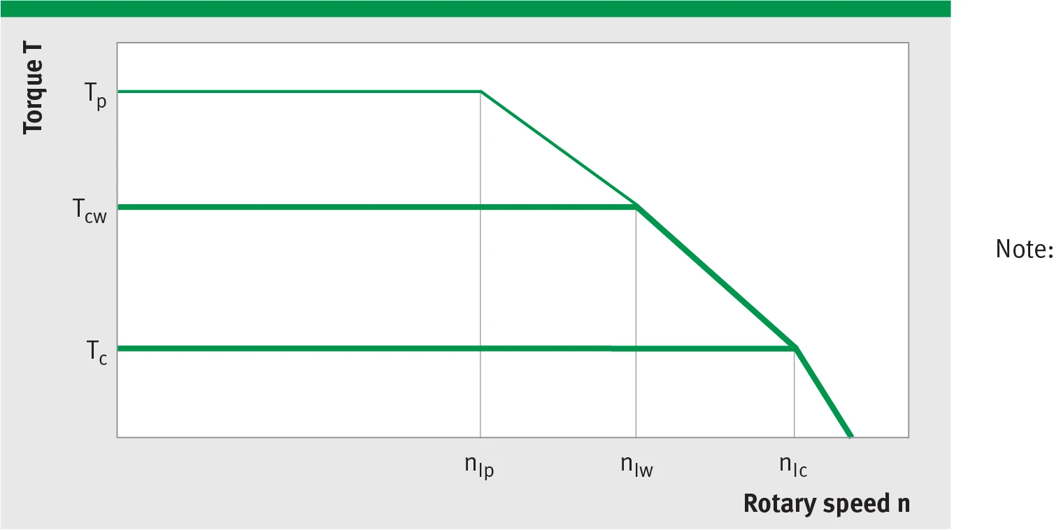
Torque-rotary speed characteristic (Tp: peak torque; Tcw: cooled continuous torque; Tc: continuous torque; nlp / nlw / nlc: corresponding limiting speeds)
The limiting speed is limited by the bearing, the measuring system or the motor oneself. The maximum speed is specified in the data sheets.
Note: At lower DC link voltages (UDCL) the limiting speed of the motor is reduced almost proportionally. This should be noted when selecting the winding version.
Winding specific speed limits are quiet proportional to UDCL.
A continuous running of these motors could be limited in a range around ncr because of additional frequency-dependent losses (see glossary). Then a further reduction of duty cycle or current is required.
Torque-Current Characteristic
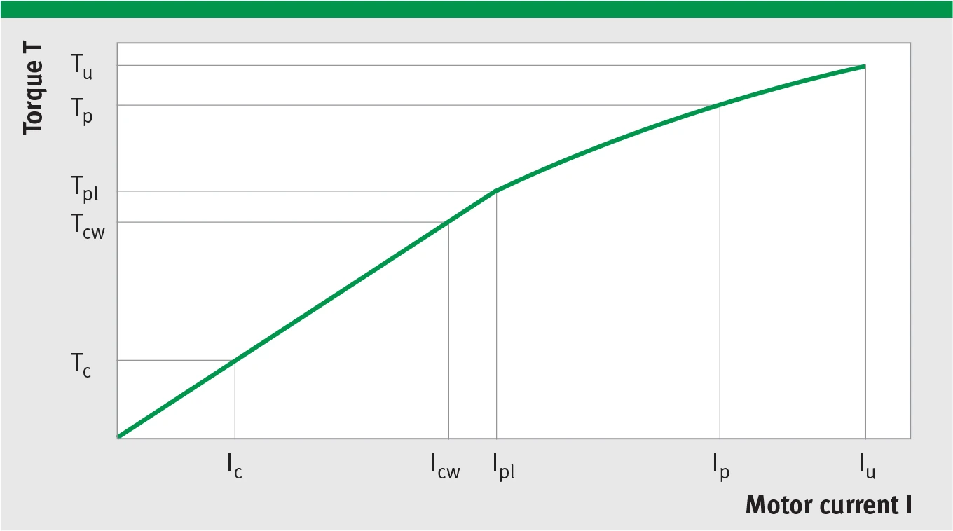
Torque-current characteristic (Tc, Tcw, Tpl, Tp, Tu with corresponding currents Ic, Icw, Ipl, Ip, Iu; curve shows magnetic saturation non-linear behavior)
Saturation Behavior
The torque increases with growing effective current linearly at first; next, the torque changes into the bent part, and then increases in a flat, linear fashion.
The bend results from the magnetic saturation of the entire magnetic circuit.