Connector Type Overview
SCHNEEBERGER offers various connector interfaces to accommodate different control systems and application requirements.
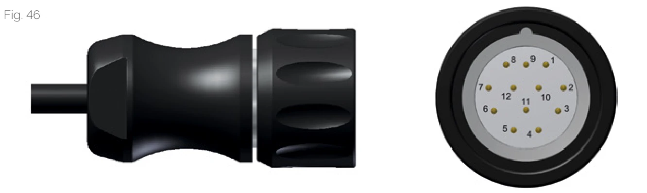
TSU/TSD 12-pin plug
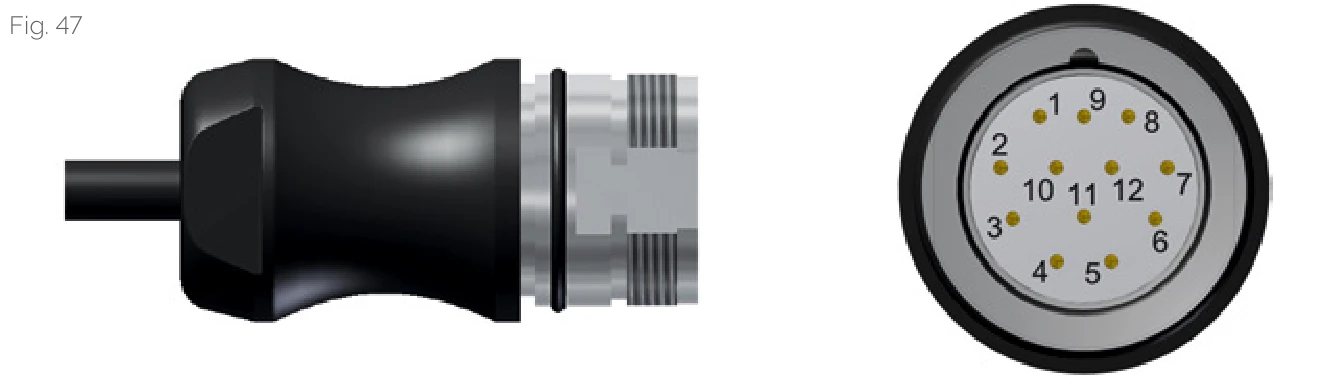
TRU/TRD 12-pin plug
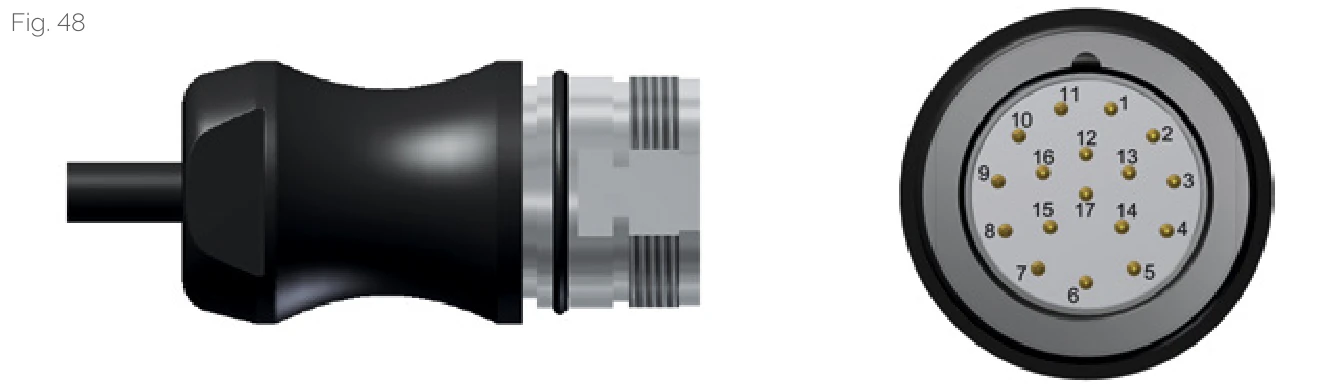
TRH 17-pin plug
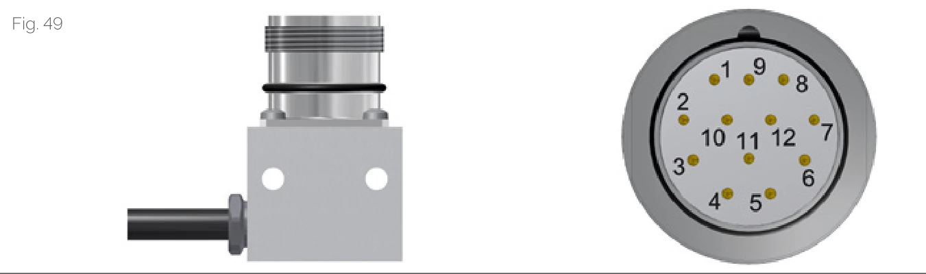
TMU/TMD mounting base
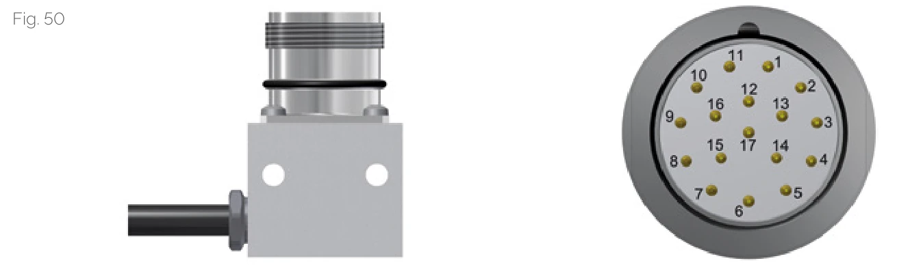
TMH 17-pin mounting base
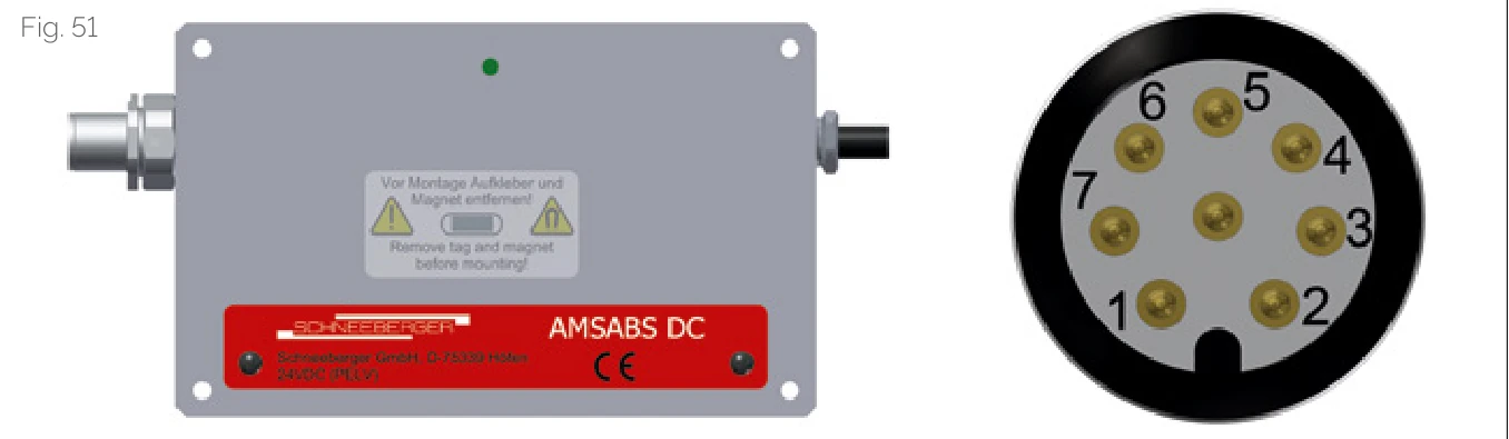
TDC 8-pin electronics housing
| Interface Code | Type | Connector Form | Cable Length |
|---|---|---|---|
| TSU / TSD | 12-pin circular connector (female) | Union nut and female thread | 3m |
| TRU / TRD | 12-pin circular connector (male) | Male thread | 3m |
| TRH | 17-pin circular connector (male) | Male thread | 3m |
| TMU / TMD | 12-pin circular connector (mounting base) | Built in a mounting base | 0.3m |
| TMH | 17-pin circular connector (mounting base) | Built in a mounting base | 0.3m |
| TDC | 8-pin circular connector (male) | Male thread built into electronics housing | - |
TSU/TRU/TMU Analog Interface
The signals are shown inverted according to differential gain. The incremental signals are displaced by exactly 90° in their phasing. The levels after differential gain of the incremental signals and of the reference signals are 1 ± 0.1 Vpp. The incremental signals supply valid values between 0.6 Vpp and 1.2 Vpp. This interface works with all standard control systems that support a 1 Vpp voltage interface.
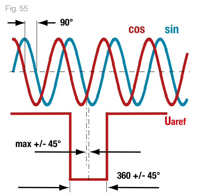
Analog voltage interface signal waveform
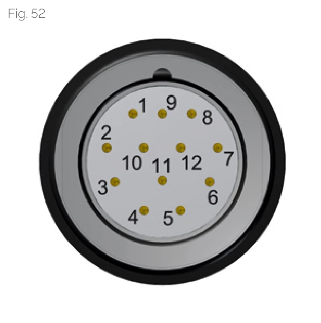
TSU/TRU/TMU pinout
Pinout Configuration
| Pin | Signal | Signal Type |
|---|---|---|
| 1 | -Ua2 | - Cosine |
| 2 | +5V Sensor | Supply voltage feed back |
| 3 | +Ua0 | Reference signal |
| 4 | -Ua0 | Reference signal |
| 5 | +Ua1 | + Sine |
| 6 | -Ua1 | - Sine |
| 7 | -Uas | NC |
| 8 | +Ua2 | + Cosine |
| 9 | - | NC |
| 10 | 0V (GND) | Supply voltage |
| 11 | 0V Sensor | Supply voltage feed back |
| 12 | +5 V | Supply voltage |
TSD/TRD/TMD Digital Interface
Incremental signals A+, A-, B+, B- and reference signals R+, R- transmit data in a complementary manner according to RS 422 standard. The diagram shows positive signals, with signal levels as follows:
| High | > 2.5 V |
|---|---|
| Low | < 0.5 V |
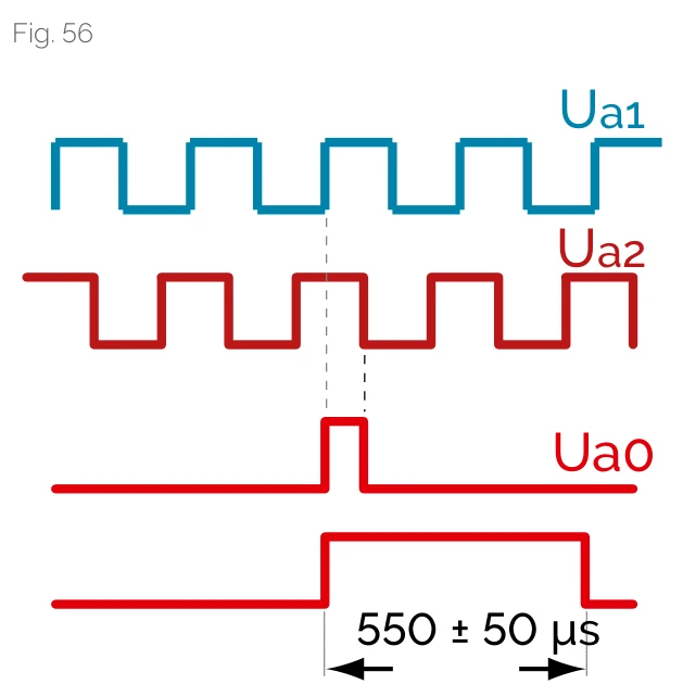
Digital interface timing diagram
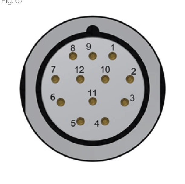
TRD/TMD pinout
Rise and fall times are less than 20 ns. Minimum signal spacing can be calculated from the maximum output frequency. Downstream electronics must be able to handle the maximum output frequency without problems.
Reference Pulse Options
Option ZN
Reference pulse is strictly synchronized with incremental signal.
Option ZF
Reference pulse is extended to 550 us +/- 50 us. This option is suitable for evaluation electronics that cannot handle multiple short-duration reference pulses.
Interpolation Factor, Maximum Output Frequency, and Reference Pulse Combinations
The following combinations apply to all read head interfaces:
| Code | Resolution | Interpolation Factor | Max Output Frequency |
|---|---|---|---|
| -010-80-ZN | 5 um | 10x | 8 MHz |
| -050-80-ZN | 1 um | 50x | 8 MHz |
| -250-80-ZN | 0.2 um | 250x | 8 MHz |
| -010-80-ZF | 5 um | 10x | 8 MHz |
| -050-80-ZF | 1 um | 50x | 8 MHz |
| -250-80-ZF | 0.2 um | 250x | 8 MHz |
Order Code Example
-010-80-ZN- 10x interpolation, maximum output frequency 8 MHz, standard reference pulse
TSD/TRD/TMD Pinout Configuration
| Pin | Signal | Signal Type |
|---|---|---|
| 1 | -Ua2 | A quad B signal |
| 2 | +5V Sensor | Supply voltage feed back |
| 3 | +Ua0 | Reference signal synchronized |
| 4 | -Ua0 | Reference signal synchronized |
| 5 | +Ua1 | A quad B signal |
| 6 | -Ua1 | A quad B signal |
| 7 | -Oas | Error signal active low, minimum duration 20 ms |
| 8 | +Ua2 | A quad B signal |
| 9 | - | NC |
| 10 | 0V (GND) | Supply voltage |
| 11 | 0V Sensor | Supply voltage feed back |
| 12 | +5 V | Supply voltage |
Absolute Interfaces TRH / TMH / TSH
Absolute position information can be transmitted via fully digital interfaces or hybrid interfaces.
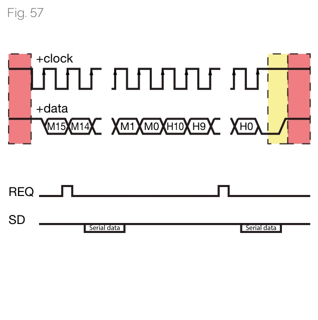
TRH/TMH/TSH interface timing diagram
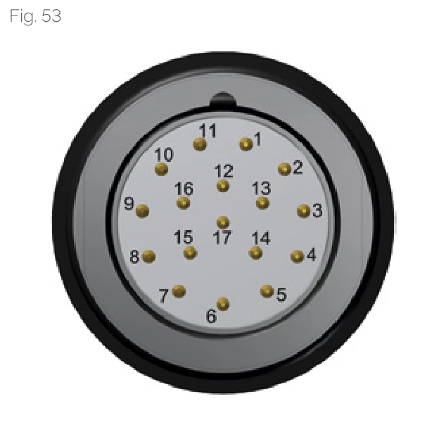
TRH/TMH/TSH pinout
Fully Digital SSI Interface
In the fully digital SSI interface, the first channel (+clock) sends clock signals from the receiver to the measuring system; the second channel (+data) simultaneously sends absolute position values from the measuring system to the downstream electronic unit.
Fanuc Serial Interface
Another fully digital interface example is the "Fanuc Serial Interface." The motor controller only sends a request signal (REQ) instead of pulses. The measuring system calculates the clock rate accordingly, which is used to send position data and supplementary data (SD) to the receiver.
SSI+SinCos Hybrid Interface
The SSI+SinCos hybrid interface only sends digital absolute initial position at power-on, then sends incremental 1 Vpp signals.
Interface Compatibility
- SSI Interface: Can connect to any commercial controller with SSI interface
- Fanuc Serial Interface: Designed specifically for Fanuc controllers
- SSI+SinCos Interface: Designed specifically for Siemens controllers
TRH/TMH/TSH Pinout Configuration (SSI / Fanuc / Mitsubishi Interface)
| Pin | Signal | Signal Type |
|---|---|---|
| 1 | +5V sensor | Supply voltage feedback |
| 2 | - | NC |
| 3 | - | NC |
| 4 | 0V sensor | Supply voltage feedback |
| 5 | - | internal parameterisation |
| 6 | TxD | internal parameterisation |
| 7 | +5V to 24V | Supply voltage |
| 8 | +CLK | + Pulse |
| 9 | -CLK | - Pulse |
| 10 | 0V (GND) | Supply voltage |
| 11 | - | inner screen |
| 12 | +Ua2 | + Cosine |
| 13 | -Ua2 | - Cosine |
| 14 | +DATA | + Data |
| 15 | +Ua1 | + Sine |
| 16 | -Ua1 | - Sine |
| 17 | -DATA | - Data |
If the controller is not using the line for supply voltage feedback, the contacts 1 and 7 and the contacts 4 and 10 can be combined to reduce the voltage drop or to permit longer cable lengths. The contacts 1 and 7, and the contacts 4 and 10, are interconnected on the AMS side.
Absolute Interface TDC (DRIVE-CLiQ)
Absolute information from the measuring system is transmitted via the DRIVE-CLiQ communication interface, a real-time serial interface for bidirectional data transmission with Siemens controllers.
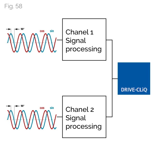
TDC DRIVE-CLiQ interface
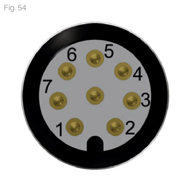
TDC pinout diagram
The measuring system connection is suitable for safety-oriented applications and supports the SAFETY INTEGRATED function available for Siemens SINAMCS and SINUMERIK controllers. The system complies with IEC 61508-1:2010 functional safety requirements.
DRIVE-CLiQ is a registered trademark of Siemens
TDC Pinout Configuration
| Pin | Signal | Function |
|---|---|---|
| 1 | +24 V | Power supply (positive) |
| 2 | (TXD, service only) | Communication with service program |
| 3 | RXP | Receive data + |
| 4 | RXN | Receive data - |
| 5 | GND (0V) | Power supply (negative) |
| 6 | TXN | Transmit data - |
| 7 | TXP | Transmit data + |
| 8 | (RXD, service only) | Communication with service program |