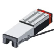
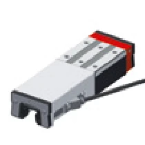
Rail Types AMSABS 4B S 15
Note: Size 15 is only available in ND and CD rail types (through-hardened versions), standard N and C types are not available.
| AMSABS 4B S 15-ND | AMSABS 4B S 15-CD |
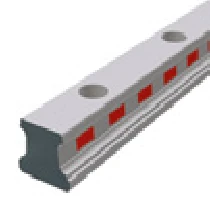 | 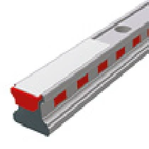 |
| Through-Hardened Standard | Through-Hardened Cover Strip |
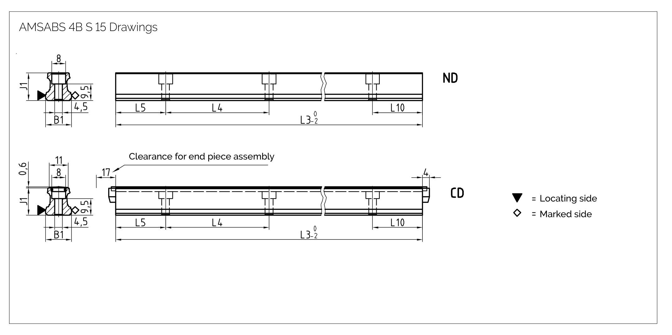
Rail Dimensional Drawing AMSABS 4B S 15
Rail Specifications AMSABS 4B S 15
| Parameter | AMSABS 4B S 15-ND | AMSABS 4B S 15-CD |
| Rail Width B1 (mm) | 15 | 15 |
| Rail Height J1 (mm) | 15.7 | 15.7 |
| Max. Single Piece Length L3 (mm) | 1500 | 1500 |
| Mounting Hole Pitch L4 (mm) | 60 | 60 |
| First/Last Hole Position L5/L10 (mm) | 28.5 | 28.5 |
| Weight per Meter (kg/m) | 1.4 | 1.3 |
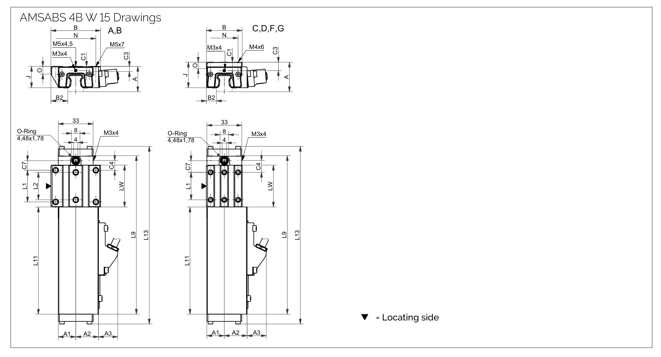
Carriage Dimensional Drawing AMSABS 4B W 15
Carriage Specifications AMSABS 4B W 15
| Parameter | AMSABS 4B W 15-A | AMSABS 4B W 15-B | AMSABS 4B W 15-C | AMSABS 4B W 15-D | AMSABS 4B W 15-F | AMSABS 4B W 15-G |
| System Height A (mm) | 24 | 24 | 28 | 28 | 24 | 24 |
| Housing Half Width, Opposite Side A1 (mm) | 16.5 | 16.5 | 16.5 | 16.5 | 16.5 | 16.5 |
| Housing Half Width, Reading Head Side A2 (mm) | 21.5 | 21.5 | 21.5 | 21.5 | 21.5 | 21.5 |
| Reading Head Projection A3 (mm) | 17.5 | 17.5 | 17.5 | 17.5 | 17.5 | 17.5 |
| Carriage Width B (mm) | 47 | 47 | 34 | 34 | 34 | 34 |
| Reference Distance B2 (mm) | 16 | 16 | 9.5 | 9.5 | 9.5 | 9.5 |
| Front Center Lube Port C1 (mm) | 4 | 4 | 8 | 8 | 4 | 4 |
| Side Lube Port Position C3 (mm) | 3.7 | 4 | 7.7 | 8 | 3.7 | 4 |
| Side Lube Port Position (2nd) C4 (mm) | 9.3 | 17.3 | 11.3 | 19.3 | 11.3 | 19.3 |
| Top Lube Port Position C7 (mm) | 9.05 | 17.05 | 11.05 | 19.05 | 11.05 | 19.05 |
| Carriage Height J (mm) | 20.4 | 20.4 | 24.4 | 24.4 | 20.4 | 20.4 |
| Outer Mounting Hole Pitch L1 (mm) | 30 | 30 | 26 | 26 | 26 | 26 |
| Inner Mounting Hole Pitch L2 (mm) | 26 | 26 | — | — | — | — |
| Carriage Length incl. Housing L9 (mm) | 149.6 | 165.5 | 165.5 | 149.6 | 149.6 | 165.5 |
| Housing Length L11 (mm) | 101.5 | 101.5 | 101.5 | 101.5 | 101.5 | 101.5 |
| Measuring Carriage Total Length L13 (mm) | 168.5 | 184.4 | 168.5 | 184.4 | 168.5 | 184.4 |
| Carriage Body Inner Length Lw (mm) | 39.6 | 55.5 | 39.6 | 55.5 | 39.6 | 55.5 |
| Side Mounting Hole Pitch N (mm) | 38 | 38 | 26 | 26 | 26 | 26 |
| Reference Height O (mm) | 7 | 7 | 6 | 6 | 6 | 6 |
Load Ratings
| Parameter | AMSABS 4B W 15-A | AMSABS 4B W 15-B | AMSABS 4B W 15-C | AMSABS 4B W 15-D | AMSABS 4B W 15-F | AMSABS 4B W 15-G |
| Static Load Capacity C₀ (N) | 19600 | 22900 | 19600 | 22900 | 19600 | 22900 |
| Dynamic Load Capacity C₁₀₀ (N) | 9000 | 11400 | 9000 | 11400 | 9000 | 11400 |
| Static Cross Moment Capacity M₀Q (Nm) | 181 | 218 | 181 | 218 | 181 | 218 |
| Static Longitudinal Moment Capacity M₀L (Nm) | 146 | 198 | 146 | 198 | 146 | 198 |
| Dynamic Cross Moment Capacity MQ (Nm) | 83 | 108 | 83 | 108 | 83 | 108 |
| Dynamic Longitudinal Moment Capacity ML (Nm) | 67 | 96 | 67 | 96 | 67 | 96 |
| Carriage Weight (kg) | 0.4 | 0.5 | 0.5 | 0.5 | 0.4 | 0.4 |
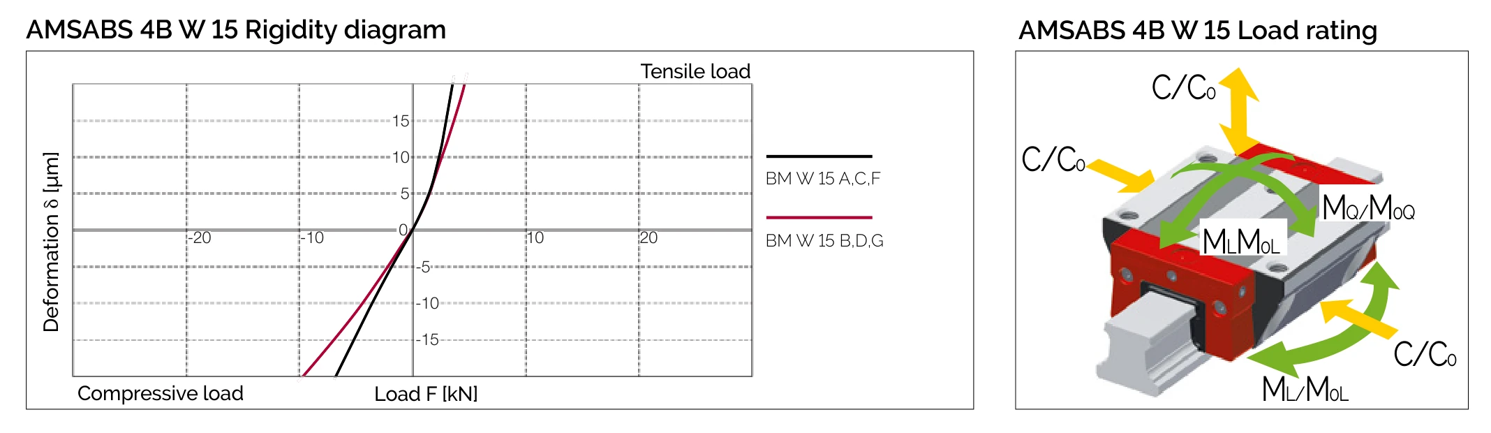
Rigidity Diagram and Load Directions AMSABS 4B W 15
Measuring System Specifications
| Measuring Principle | Magneto-resistive absolute encoding (magnetically hard periodic N-S scale) |
| Signal Period | 200 µm |
| Accuracy | ± 5 µm / 1000 mm; ± 2 µm / 40 mm |
| Periodic Error | ± 0.7 µm |
| Resolution | max. 0.09765625 µm (TM1 configuration 0.05 µm; TS2 configuration 0.050 µm) |
| Hysteresis | < 0.5 µm |
| Supply Voltage | 5 V ± 10% or 24 V ± 10% (24 V for TS2 configuration, PELV EN 50178) |
| Max. Speed | 3 m/s |
| Operating Temperature | 0 °C ~ +70 °C |
| Protection Rating | IP68 |
Source: MONORAIL and AMS Product Catalogue §4.6 General technical data (p.39).
Order Code Examples
Rail Order Code
1x AMSABS 4B S 15-ND-G2-KC-R12-1000-28.5-28.5-CN-TA1
- AMSABS 4B S 15 = AMSABS 4B Rail Size 15
- ND = Through-Hardened Standard
- G2 = Accurate
- KC = Standard straightness
- R12 = Locating side at bottom, scale at top
- 1000 = Rail length 1000 mm
- 28.5-28.5 = First/last hole position
Carriage Order Code
1x AMSABS 4B W 15-A-P1-G2-V1-R1-CN-S10-LN-TMH-TS1
- AMSABS 4B W 15 = AMSABS 4B Carriage Size 15
- A = Standard type carriage
- P1 = Reading head position right top
- G2 = Accurate
- V1 = Low preload
- R1 = Reference bottom
- CN = No coating
- S10 = Left center lubrication port
- LN = Oil protect
- TMH = Absolute interface, cable 0.3 m
- TS1 = Hybrid: cycle synchronous serial + analogue 1 Vpp configuration