Permissible Compressive Axial Load Fperm
Permissible Compressive Axial Load
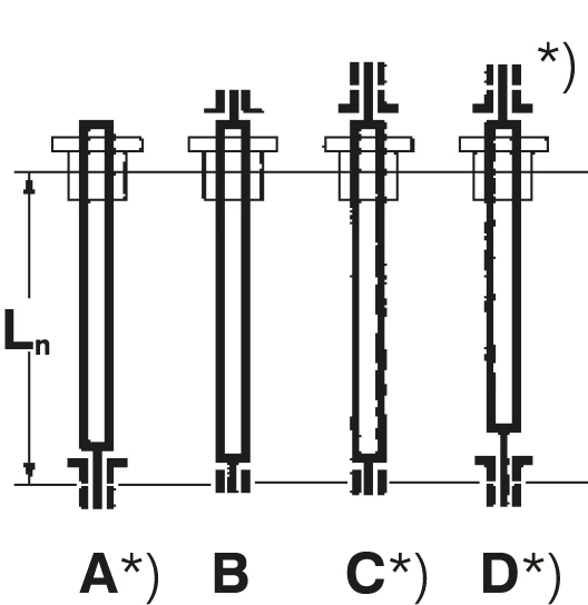
*) Directionally stable mounting
Bearing Arrangement Types
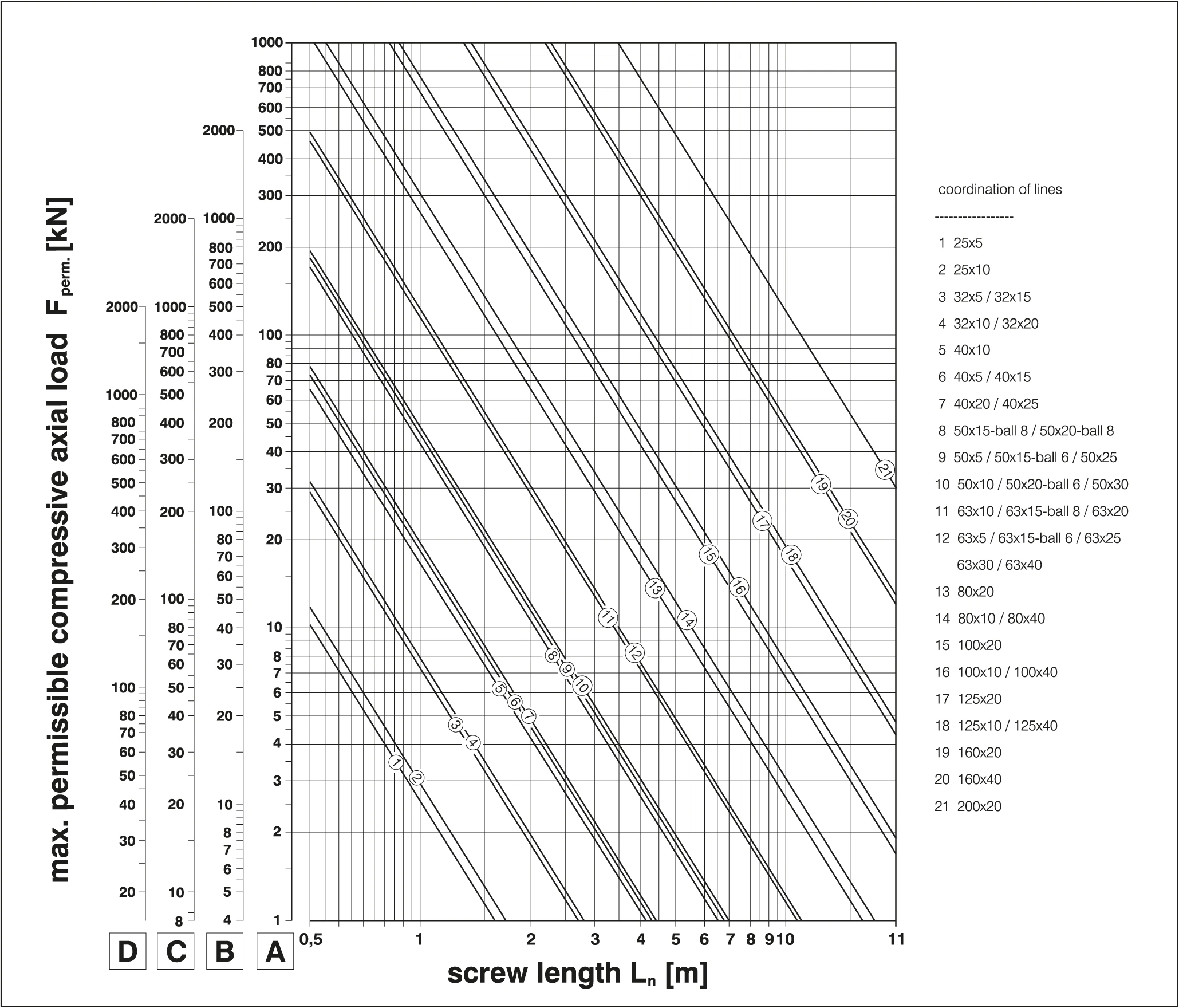
The permissible axial load can be determined from the chart based on screw bearing arrangement, nominal diameter d0 × lead P, and screw length Ln.
For compressive axial load Fk, the chart includes a threefold safety factor (ν = 3).
The static load rating C0am is the load limit that causes plastic deformation of 10-4 × ball diameter under static conditions.
See data sheets for C0am
Steps for Increasing the Permissible Compressive Axial Load
Steps for Increasing the Permissible Compressive Axial Load
Use Bearing Arrangement D
Double-end fixed arrangement provides the highest axial load capacity
Apply Tensile Load
Apply tensile load to the screw in arrangement A or C cases
Increase Nominal Diameter
Larger diameter can withstand higher compressive loads
Reduce Compressive Load
Share load through hydraulic or counterweight methods
Bearing Arrangement Reference Table
Bearing Arrangement Reference
| Arrangement | Description | English | kL | Directionally stable |
|---|---|---|---|---|
| A | Fixed–Free | Fixed–Free | kL = 1.68 | Yes |
| B | Supported–Supported | Supported–Supported | kL = 4.68 | No |
| C | Fixed–Supported | Fixed–Supported | kL = 7.31 | Yes |
| D | Fixed–Fixed | Fixed–Fixed | kL = 10.60 | Yes |