Drawing
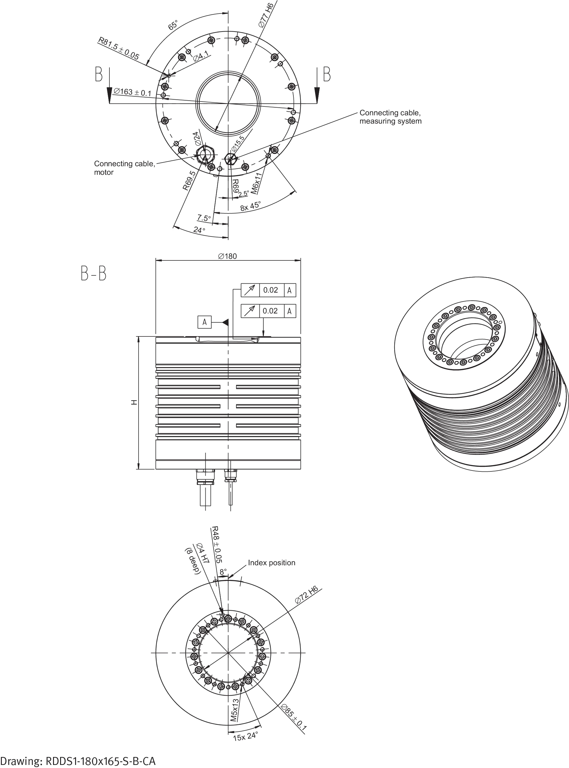
Figure: RDDS1-180x165-S-B-CA Drawing — includes top view, B-B cross-section, and isometric view. The drawing indicates the connecting cable for the measuring system, connecting cable for the motor, and key fit dimensions: stage plate inner diameter 72 H6 and base plate inner diameter 77 H6.
System Data
Tolerance Note
Tolerance range for all values: ±5%. On housing of the rotary system the maximum temperature of 60 °C must not be exceeded by default.
* In few cases the limiting speed is limited by the winding version of the motor.
| System Data | Symbol | Unit | RDDS1- 180x110 | RDDS1- 180x137.5 | RDDS1- 180x165 | RDDS1- 180x192.5 |
|---|---|---|---|---|---|---|
| Diameter × height | DxH | mm | 180x110 | 180x137.5 | 180x165 | 180x192.5 |
| Inner diameter: stage plate | dsp | mm | 72 | 72 | 72 | 72 |
| Inner diameter: base plate | dbp | mm | 77 | 77 | 77 | 77 |
| Measuring system 1 Vpp | ||||||
| — Resolution (inc) | inc | inc | 5400 | 5400 | 5400 | 5400 |
| — Resolution (inc) | inc | inc | 18000 | 18000 | 18000 | 18000 |
| Limiting speed of bearing | nlim | rpm | 340 | 340* | 340* | 340* |
| Mass | m | kg | 11.6 | 15.7 | 19.8 | 23.9 |
| Moment of inertia | J | kgm2 | 0.0051 | 0.0064 | 0.0077 | 0.009 |
| Axial/radial runout | SR/KR | µm | ±10 | ±10 | ±10 | ±10 |
| Absolute accuracy | Djabs | arcsec | ≤30 | ≤30 | ≤30 | ≤30 |
| Repeatability | Djrep | arcsec | ≤5 | ≤5 | ≤5 | ≤5 |
| Axial load | Fax | N | 641.0 | 641.0 | 641.0 | 641.0 |
| Radial load | Frad | N | 104.0 | 104.0 | 104.0 | 104.0 |
| Moment impact (tilting torque) | Ttilt | Nm | 27.5 | 27.5 | 27.5 | 27.5 |
Motor Specifications – Independent of Winding
Tolerance Note
Tolerance range for all values: ±5%. Tolerance range for values “ripple torque” and “power loss”: ±10%.
The stated motor data relate to a fixing of the rotary system on a mounting plate with a surface of ca. 73,600 mm2.
| Motor Specifications | Symbol | Unit | RDDS1- 180x110 | RDDS1- 180x137.5 | RDDS1- 180x165 | RDDS1- 180x192.5 |
|---|---|---|---|---|---|---|
| Number of pole pairs | P | 13 | 13 | 13 | 13 | |
| Maximum operating voltage | U | V | 600 | 600 | 600 | 600 |
| Ultimate torque at Iu | Tu | Nm | 37 | 74 | 111 | 147 |
| Peak torque (saturation range) at Ip | Tp | Nm | 31 | 63 | 95 | 125 |
| Peak torque (linear range) at Ipl | Tpl | Nm | 23 | 46 | 69 | 92 |
| Continuous torque – water cooled – at Icw | Tcw | Nm | 18 | 41 | 66 | 91 |
| Continuous torque – not cooled – at Ic | Tc | Nm | 8 | 17 | 23 | 29 |
| Stall torque – water cooled – at Isw | Tsw | Nm | 13 | 29 | 47 | 65 |
| Stall torque – not cooled – at Is | Ts | Nm | 6 | 12 | 17 | 21 |
| Ripple torque (cogging) at I = 0 | Tr | Nm | 0.1 | 0.2 | 0.3 | 0.4 |
| Power loss at Tp (statical, 25 °C) | Plp | W | 1193 | 1764 | 2345 | 2905 |
| Power loss at Tpl (statical, 25 °C) | Plpl | W | 466 | 689 | 916 | 1135 |
| Power loss at Tcw | Plw | W | 361 | 722 | 1089 | 1444 |
| Power loss at Tc (statical, 25 °C) | Plc | W | 66 | 105 | 119 | 131 |
| Thermical resistance (water cooled) | Rth | K/W | 0.277 | 0.139 | 0.092 | 0.069 |
| Motor constant (at 25 °C) | km | Nm/√W | 0.99 | 1.64 | 2.14 | 2.55 |
| Cooling-water flow-rate | dV/dt | l/min | 1.03 | 2.06 | 3.11 | 4.13 |
| Cooling-water temperature-difference | Δϑ | K | 5.00 | 5.00 | 5.00 | 5.00 |
Winding Specifications — RDDS1-180x110 & RDDS1-180x137.5
Note: Tolerance range for value “resistance”: ±10%. Tolerance range for value “inductance”: ±15%. Tolerance range for all other values: ±5%.
* “Limiting speed for continuous running” — See glossary.
| Winding Specifications | Symbol | Unit | RDDS1-180x110 WL | RDDS1-180x110 WM | RDDS1-180x110 WH | RDDS1-180x137.5 WL | RDDS1-180x137.5 WM | RDDS1-180x137.5 WH |
|---|---|---|---|---|---|---|---|---|
| Torque constant | kT | Nm/Arms | 3.4 | 1.7 | 1.2 | 6.7 | 3.4 | 2.4 |
| Back EMF constant | ku | Vs/rad | 2.8 | 1.4 | 1.0 | 5.5 | 2.8 | 1.9 |
| Limiting speed — UDCL = 280 V | ||||||||
| at Ip, UDCL = 280 V | nlp | rpm | 374 | 855 | 1264 | 156 | 403 | 610 |
| at Icw, UDCL = 280 V | nlw | rpm | 629 | 1352 | 1974 | 265 | 605 | 896 |
| at Ic, UDCL = 280 V | nlc | rpm | 817 | 1694 | 2450 | 391 | 827 | 1203 |
| Limiting speed — UDCL = 600 V | ||||||||
| at Ip, UDCL = 600 V | nlp | rpm | 925 | 1943 | 2817 | 439 | 950 | 1388 |
| at Icw, UDCL = 600 V | nlw | rpm | 1459 | 3010 | 4344 | 655 | 1381 | 2005 |
| at Ic, UDCL = 600 V | nlc | rpm | 1866 | 3784 | 5436 | 913 | 1867 | 2689 |
| Limiting speed for continuous running* | ncr | rpm | 462 | 462 | 462 | 462 | 462 | 462 |
| Electrical resistance, phase to phase (25 °C) | R25 | Ω | 6.6 | 1.7 | 0.8 | 9.8 | 2.5 | 1.2 |
| Inductance, phase to phase | L | mH | 27.1 | 6.8 | 3.3 | 54.3 | 13.6 | 6.6 |
| Ultimate current | Iu | Arms | 13.7 | 27.3 | 39.1 | 13.7 | 27.3 | 39.1 |
| Peak current (saturation range) | Ip | Arms | 10.9 | 21.9 | 31.3 | 10.9 | 21.9 | 31.3 |
| Peak current (linear range) | Ipl | Arms | 6.8 | 13.7 | 19.6 | 6.8 | 13.7 | 19.6 |
| Continuous current at Plw (water cooled) | Icw | Arms | 5.3 | 10.6 | 15.1 | 6.1 | 12.3 | 17.6 |
| Continuous current at Plc (not cooled) | Ic | Arms | 2.4 | 4.8 | 6.9 | 2.5 | 5.0 | 7.1 |
| Stall current at zero speed (water cooled) | Isw | Arms | 3.7 | 7.5 | 10.7 | 4.4 | 8.7 | 12.5 |
| Stall current at zero speed (not cooled) | Is | Arms | 1.7 | 3.4 | 4.9 | 1.8 | 3.5 | 5.1 |
| Maximum winding temperature | ϑ | °C | 130 | 130 | 130 | 130 | 130 | 130 |
| Interrupting sensor temperature | ϑ | °C | 100 | 100 | 100 | 100 | 100 | 100 |
Winding Specifications — RDDS1-180x165 & RDDS1-180x192.5
Note: Tolerance range for value “resistance”: ±10%. Tolerance range for value “inductance”: ±15%. Tolerance range for all other values: ±5%.
* “Limiting speed for continuous running” — See glossary.
| Winding Specifications | Symbol | Unit | RDDS1-180x165 WL | RDDS1-180x165 WM | RDDS1-180x165 WH | RDDS1-180x192.5 WL | RDDS1-180x192.5 WM | RDDS1-180x192.5 WH |
|---|---|---|---|---|---|---|---|---|
| Torque constant | kT | Nm/Arms | 10.2 | 5.1 | 3.6 | 13.5 | 6.7 | 4.7 |
| Back EMF constant | ku | Vs/rad | 8.3 | 4.2 | 2.9 | 11.0 | 5.5 | 3.9 |
| Limiting speed — UDCL = 280 V | ||||||||
| at Ip, UDCL = 280 V | nlp | rpm | 78 | 249 | 388 | 37 | 173 | 280 |
| at Icw, UDCL = 280 V | nlw | rpm | 149 | 370 | 558 | 95 | 261 | 401 |
| at Ic, UDCL = 280 V | nlc | rpm | 254 | 546 | 798 | 188 | 410 | 601 |
| Limiting speed — UDCL = 600 V | ||||||||
| at Ip, UDCL = 600 V | nlp | rpm | 273 | 614 | 905 | 192 | 452 | 672 |
| at Icw, UDCL = 600 V | nlw | rpm | 403 | 870 | 1271 | 285 | 633 | 930 |
| at Ic, UDCL = 600 V | nlc | rpm | 600 | 1234 | 1780 | 449 | 930 | 1343 |
| Limiting speed for continuous running* | ncr | rpm | 462 | 462 | 462 | 462 | 462 | 462 |
| Electrical resistance, phase to phase (25 °C) | R25 | Ω | 13.1 | 3.3 | 1.6 | 16.2 | 4.0 | 2.0 |
| Inductance, phase to phase | L | mH | 81.9 | 20.5 | 10.0 | 108.6 | 27.1 | 13.3 |
| Ultimate current | Iu | Arms | 13.7 | 27.3 | 39.1 | 13.7 | 27.3 | 39.1 |
| Peak current (saturation range) | Ip | Arms | 10.9 | 21.9 | 31.3 | 10.9 | 21.9 | 31.3 |
| Peak current (linear range) | Ipl | Arms | 6.8 | 13.7 | 19.6 | 6.8 | 13.7 | 19.6 |
| Continuous current at Plw (water cooled) | Icw | Arms | 6.5 | 13.1 | 18.7 | 6.8 | 13.5 | 19.4 |
| Continuous current at Plc (not cooled) | Ic | Arms | 2.3 | 4.6 | 6.6 | 2.2 | 4.3 | 6.2 |
| Stall current at zero speed (water cooled) | Isw | Arms | 4.6 | 9.3 | 13.3 | 4.8 | 9.6 | 13.8 |
| Stall current at zero speed (not cooled) | Is | Arms | 1.6 | 3.3 | 4.7 | 1.5 | 3.1 | 4.4 |
| Maximum winding temperature | ϑ | °C | 130 | 130 | 130 | 130 | 130 | 130 |
| Interrupting sensor temperature | ϑ | °C | 100 | 100 | 100 | 100 | 100 | 100 |