Interactive Pvs / Mds Calculator
Preload infeed force Pvs and tightening torque Mds
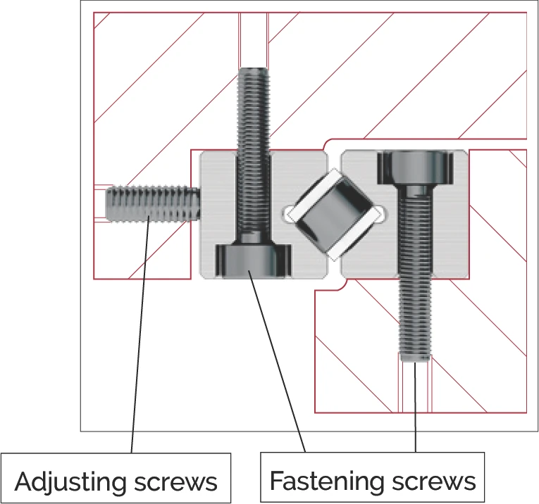
The size of the preload is guided by the intended use of the guideways. A high preload:
- … increases rigidity of the guideway and guarantees zero-backlash
- … reduces moment loads and maximum loads on the rolling elements
- … increases displacement resistance
- … reduces the service life
A positive effect of preload is achieved with 5% – 20% of the permissible load C.
General approach
The preload can be consistently set using a torque wrench. In so doing, the friction between screw and tapped fixing hole must be taken into account (to be determined by means of tests).
When using wedge adjusters or adjusting plates, the ideal preload must be determined based on the elastic total deformation δA (see chapter 12.5) and the deformation of the connecting structure.
When setting an R-guideway with cage type EE, the cage must first be slightly compressed before the rollers are applied.
As mentioned above, the preload increases the rigidity of the guideway. A high preload, however, requires a stable connecting structure. Otherwise, unwanted edge loads occur to rollers and needles as a result of angular errors, which in turn has a negative impact on load carrying capacity.
Procedure for linear guideways
A guideway is normally set with zero-backlash using adjusting screws. A zero-backlash, uniform sequence is only achieved when advancing exclusively takes place where the cage with the rolling elements is located (see also chapter 13.9).
At least one adjusting screw must be provided per fastening screw, the thread size of which should match the fastening screw. In the case of overrunning cages, the shorter rail should preferably be advanced.
Example calculation for the infeed force per adjusting screw (Pvs) and its tightening torque (Mds)
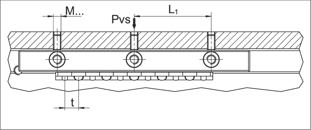
Required information per calculation:
- Linear guide type R 3, L₁ = 25 mm
- Roller cage type AC 3, t = 5 mm
- C = 130 N
- Diameter of the adjusting screw = M4
- Factor f (rollers = 1; balls / needles = 2) f = 1
- Preload p (2% to 20% of C) p = 10%
- Factor a in cm (as per the following table)
Thread and factor a
| Thread | Factor a |
|---|---|
| M2 | 0.0238 |
| M2.5 | 0.0294 |
| M3 | 0.035 |
| M4 | 0.0469 |
| M5 | 0.058 |
| M6 | 0.0699 |
| M8 | 0.0926 |
| M10 | 0.1152 |
| M12 | 0.1378 |
| M14 | 0.1591 |
| M16 | 0.1811 |
Calculation of the infeed force per adjusting screw Pvs
Pvs = L₁ / t · C · p / 100 · f
Pvs = 25 / 5 · 130 · 10 / 100 · 1 = 65 N
Calculation of tightening torque Mds
Mds = Pvs · a
Mds = 65 · 0.0469 = 3.05 Ncm
Other technical possibilities for preloading linear guideways include:
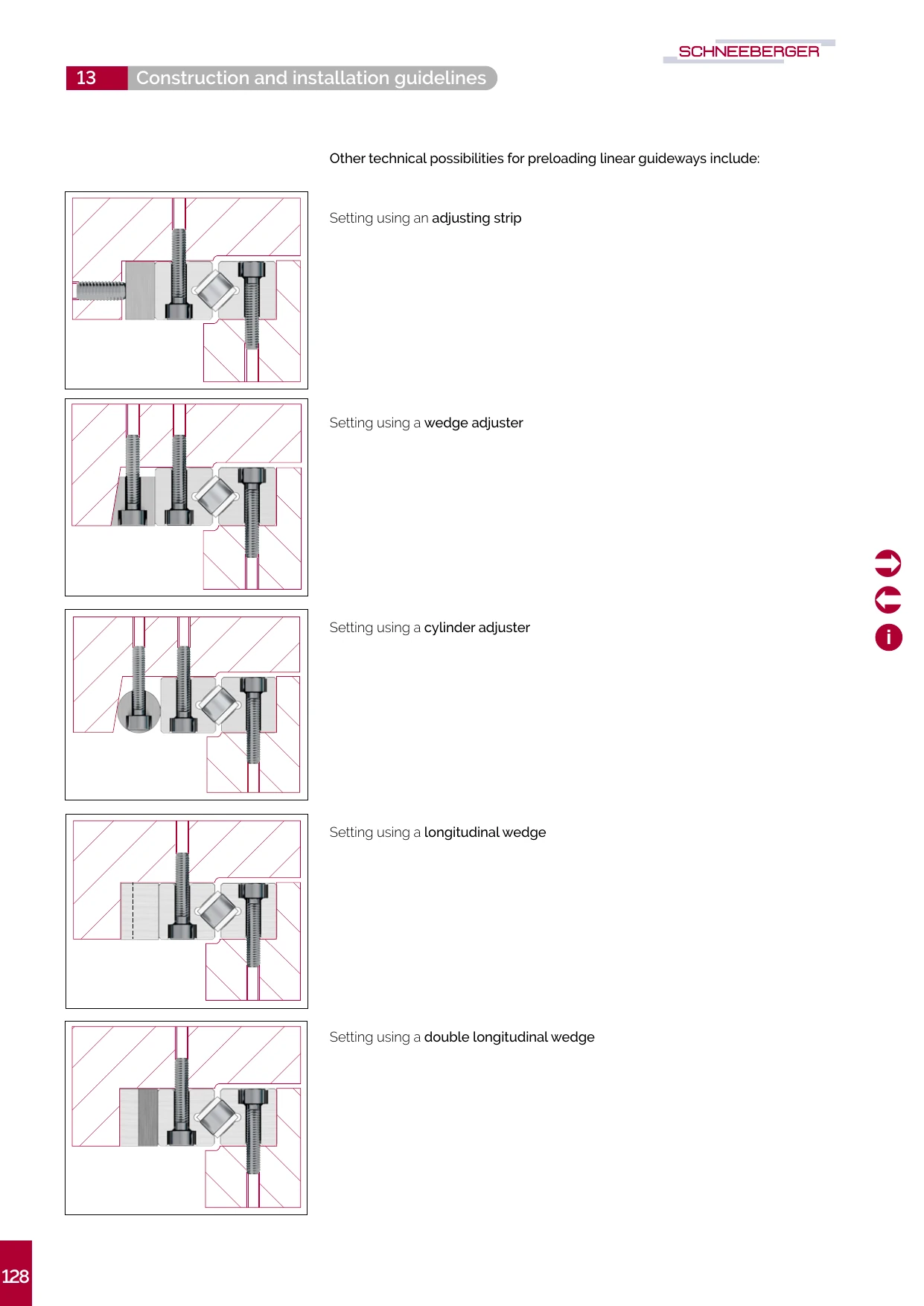
- Setting using an adjusting strip — preload set with an adjusting strip
- Setting using a wedge adjuster — preload set with a wedge adjuster
- Setting using a cylinder adjuster — preload set with a cylinder adjuster
- Setting using a longitudinal wedge — preload set with a longitudinal wedge
- Setting using a double longitudinal wedge — preload set with a double longitudinal wedge
Procedure when preloading recirculating units (SK, SKD, SKC and SR)
A recirculating unit is normally set with zero-backlash using adjusting screws. At least one adjusting screw must be provided per fastening screw, the thread size of which should match the fastening screw.
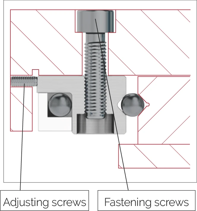
Example calculation for the infeed force per adjusting screw (Pvs) and its tightening torque (Mds)
Required information per calculation:
- Recirculating unit SK 6-100
- Diameter of the adjusting screw = M4
- Number of adjusting screws N = 2
- Factor f (rollers = 1; balls = 2) f = 2
- Preload p (5% to 20% of C) p = 10%
- C = 715 N
- Factor a in cm (as per the following table)
Thread and factor a
| Thread | Factor a |
|---|---|
| M2 | 0.0238 |
| M2.5 | 0.0294 |
| M3 | 0.035 |
| M4 | 0.0469 |
| M5 | 0.058 |
| M6 | 0.0699 |
| M8 | 0.0926 |
| M10 | 0.1152 |
| M12 | 0.1378 |
| M14 | 0.1591 |
| M16 | 0.1811 |
Calculation of the infeed force per adjusting screw Pvs
Pvs = C / N · p / 100 · f
Pvs = 715 / 2 · 10 / 100 · 2 = 71.5 N
Calculation of tightening torque Mds
Mds = Pvs · a
Mds = 71.5 · 0.0469 = 3.35 Ncm
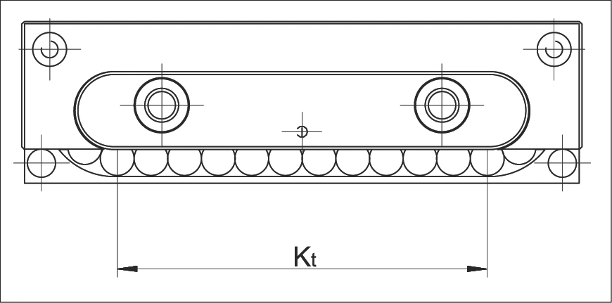
Note: the advance must always remain within the load-bearing length Kt!
Procedure for recirculating unit NRT with preload wedge type NRV
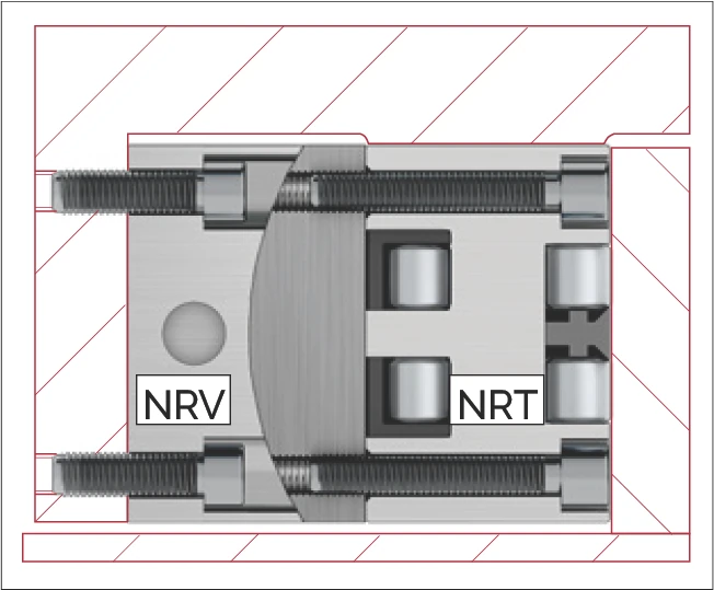
For preload using preload wedge NRV, the following infeed values apply:
Infeed values for preload wedge NRV
| Type | Size | Max. adjustment range (height, mm) | Height difference per revolution of the preload screw A |
|---|---|---|---|
| NRV | 19077 | 0.35 | 0.0350 |
| 26111 | 0.40 | 0.0625 | |
| 26132 | 0.40 | 0.0625 | |
| 38144 | 0.40 | 0.0750 |
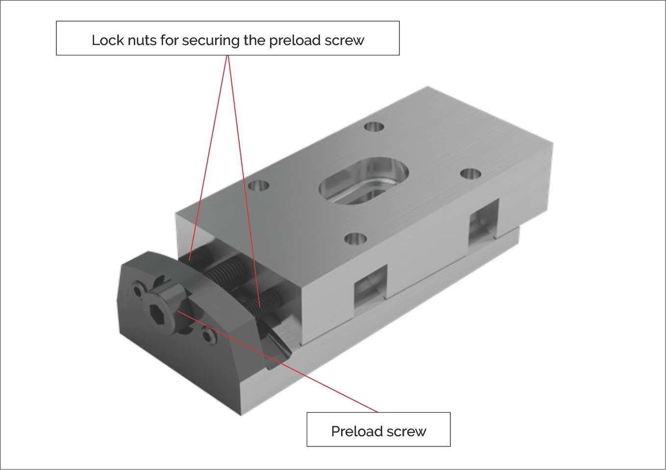
Note: after successfully setting the preload, always tighten the two lock nuts alternately and use the wrench applying the same amount of torque!
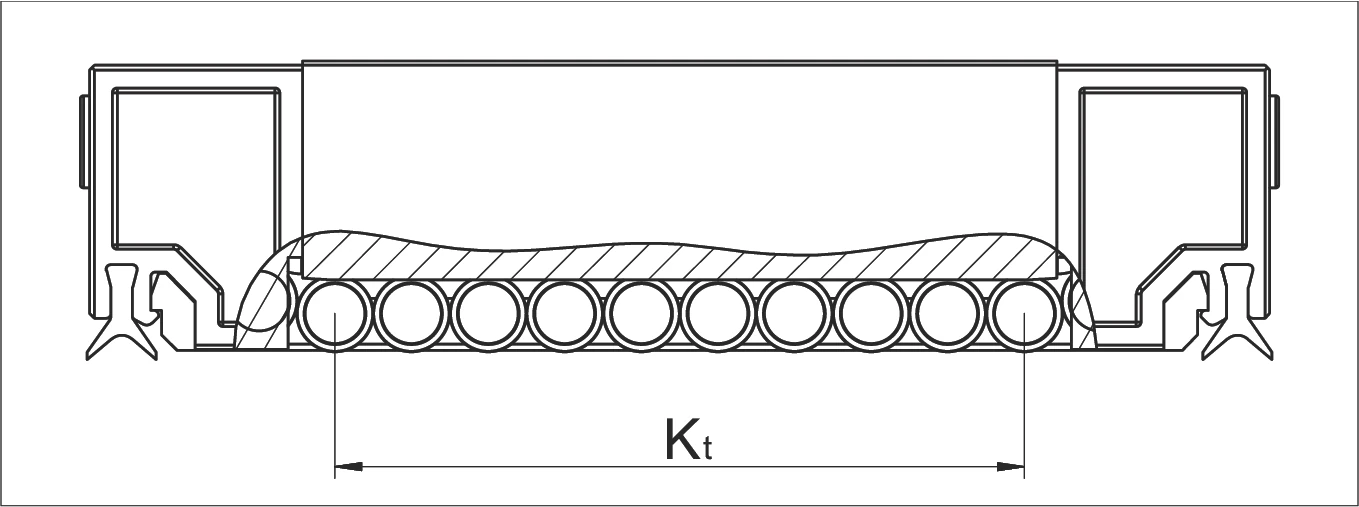
Important: if preloading takes place without preload wedge NRV, it is important to ensure that the advance always remains within the load-bearing length Kt.
Other technical possibilities for preloading NRT include:
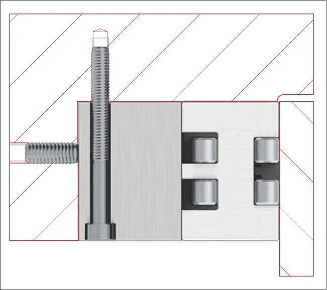
Setting using an intermediate plate
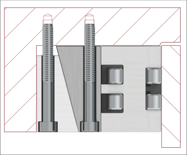
Setting using a wedge adjuster
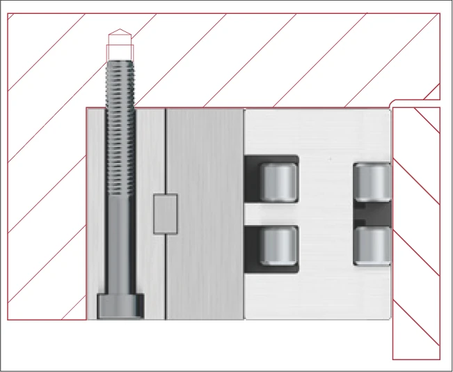
Setting using a double longitudinal wedge