1.2.1 Carriage and Guide Rail
The SCHNEEBERGER MONORAIL guideway system consists of guide rails and carriages containing rolling elements. The rolling elements run in raceways enclosed within the carriage, enabling the carriage to achieve unlimited linear motion on the guide rail. The rolling element raceways are divided into load zones and return zones.
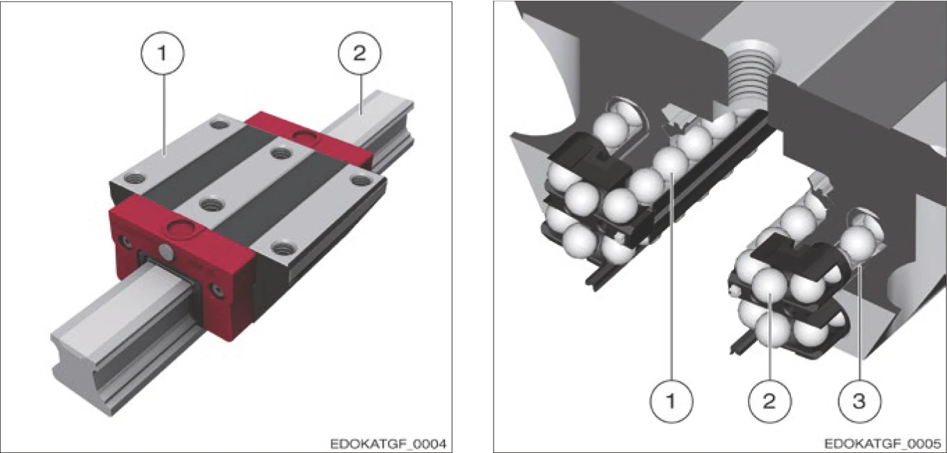
Figure 1.5 - Carriage and guide rail construction: 1 Carriage 2 Guide rail
Rolling Element Recirculating Unit
The rolling element recirculating unit is located inside the carriage and contains the load zone and return zone. In the load zone, rolling elements bear and transmit external loads; in the return zone, rolling elements return in an unloaded state.
Reference Surfaces and Fixing
SCHNEEBERGER MONORAIL guideways are fixed to the surrounding structure via the guide rail base surface and lateral locating surface. The support surface of the guide rail base is designed by SCHNEEBERGER as the complete surface area to achieve the greatest possible rigidity in the join between the guide rail and the surrounding structure.
The lateral locating surface is standard designed on one side for lateral support and orientation with the connecting structure. Dual-sided locating surfaces can also be provided upon request.
Fixing Hole Configuration
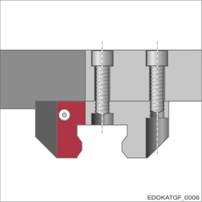
Using threaded fixing holes
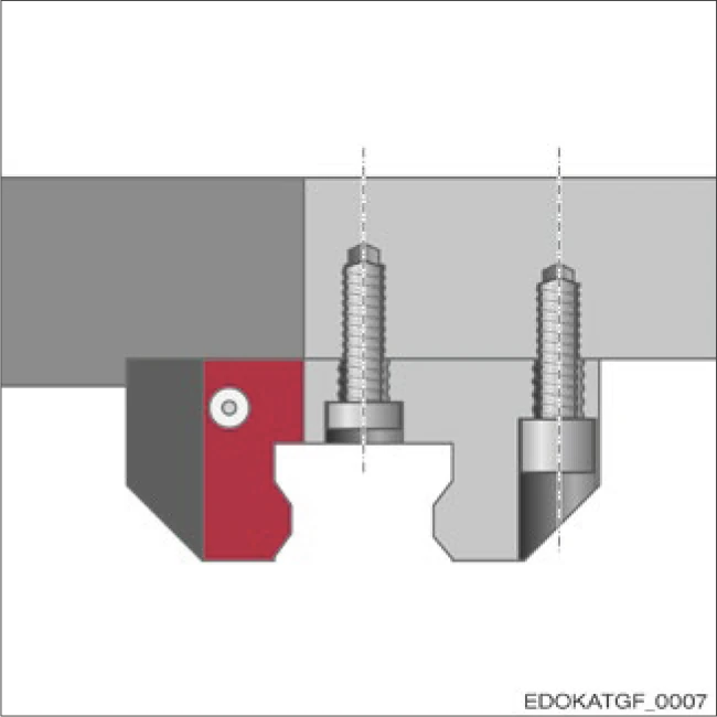
Using carriage fixing holes as through holes
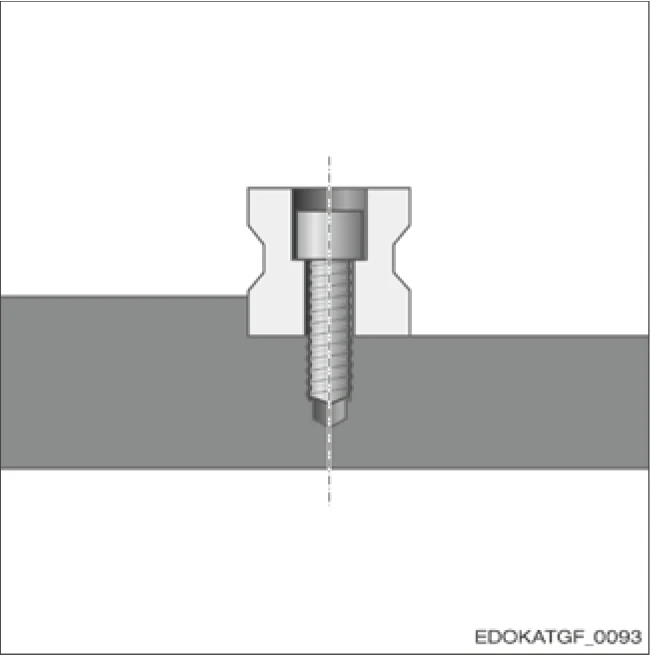
Guide rail with through holes
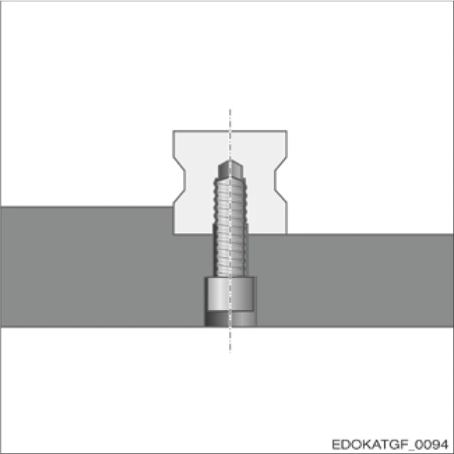
Guide rail with threaded fixing holes from below
Accuracy Requirements
The quality of mounting and locating surfaces and their mutual positional relationship affects the geometric accuracy and service life of guideways. Therefore, these surfaces need to be precision machined to high quality standards.
1.2.2 Individual Components and Accessories
SCHNEEBERGER MONORAIL guideway carriages consist of multiple components. The core is the load-bearing body made of high-grade ball bearing steel, with fixing holes and raceways and return bores for rolling elements.
Rolling Elements
Rollers or balls are used as rolling elements, all made of hardened ball bearing steel.
Guiding Elements
Another component of the carriage body is the synthetic guiding element with integrated longitudinal wipers.
Recirculating Unit
The recirculating unit for rolling elements is also a component of the carriage body.
End Plate
The end plate with integrated transverse wipers seals the carriage front and is responsible for lubricant distribution.
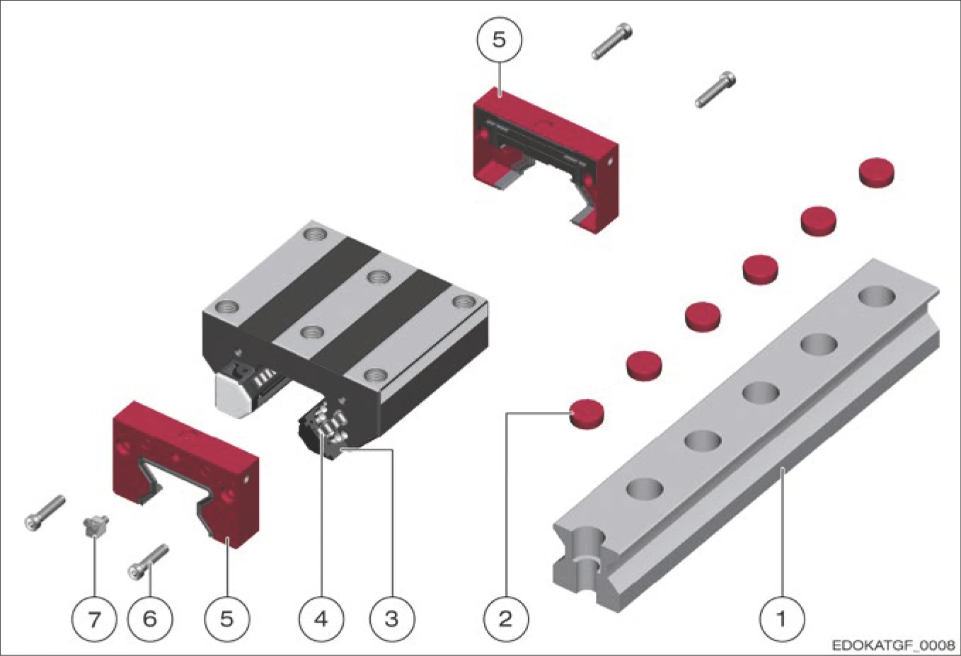
Figure 1.6 - Basic equipment of MONORAIL MR roller guideway
Basic equipment components:
Accessory Options
Carriages can be upgraded with accessories, such as additional wipers, metal scrapers, or lubrication plates, which are mounted in front of the end plate to support system adaptation for specific applications.
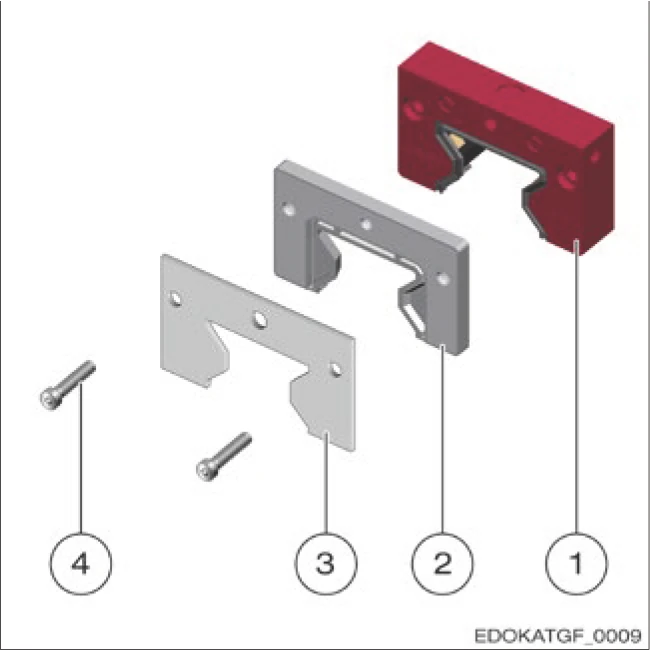
Figure 1.7 - Accessory options for MONORAIL MR roller guideway
Accessory options:
1.2.3 Types and Design Principles
Applicable Standards
SCHNEEBERGER MONORAIL guideways are available in various sizes and types. To establish consistent standards for these machine elements, the most important design elements have been compiled in industry standard DIN 645 Part 1.
Important product standards
Individual components
Rolling Element Arrangement
The number and arrangement of rolling element rows depends on rolling element shape, roller contact, available installation space, transmittable forces, and other factors. There are guideways with two, four, or more rows of rolling elements.
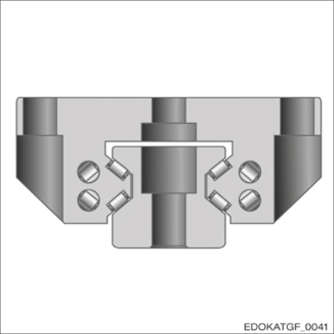
Guideway Type:
SCHNEEBERGER MONORAIL roller guideway
Geometry:
- 4 rows
- Line contact
- O-geometry
SCHNEEBERGER Products:
- MONORAIL MR
- MONORAIL AMS 3B
- MONORAIL AMSABS 3B
- MONORAIL AMSA 3L
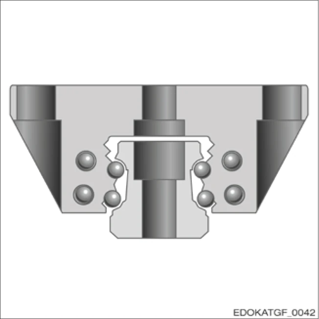
Guideway Type:
SCHNEEBERGER MONORAIL ball guideway
Geometry:
- 4 rows
- 2-point contact
- O-geometry
SCHNEEBERGER Products:
- MONORAIL BM
- MONORAIL BZ
- MONORAIL AMS 4B
- MONORAIL AMSABS 4B
X-Geometry and O-Geometry
The raceway arrangement of profiled rail guideways is distinguished between X-geometry and O-geometry. With so-called O-geometry, the rolling element raceways are offset by 90°, enabling a larger internal spacing. Therefore, guideways can consistently withstand high load forces and moments from all directions.
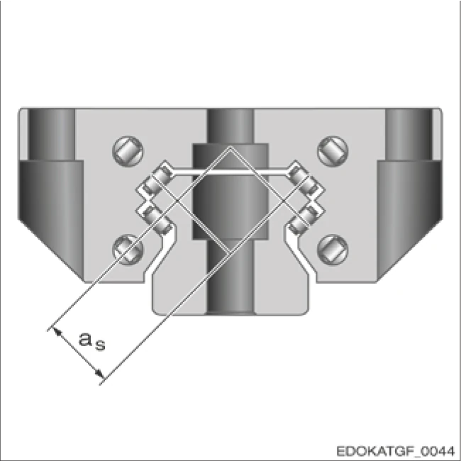
X-geometry with spacing as
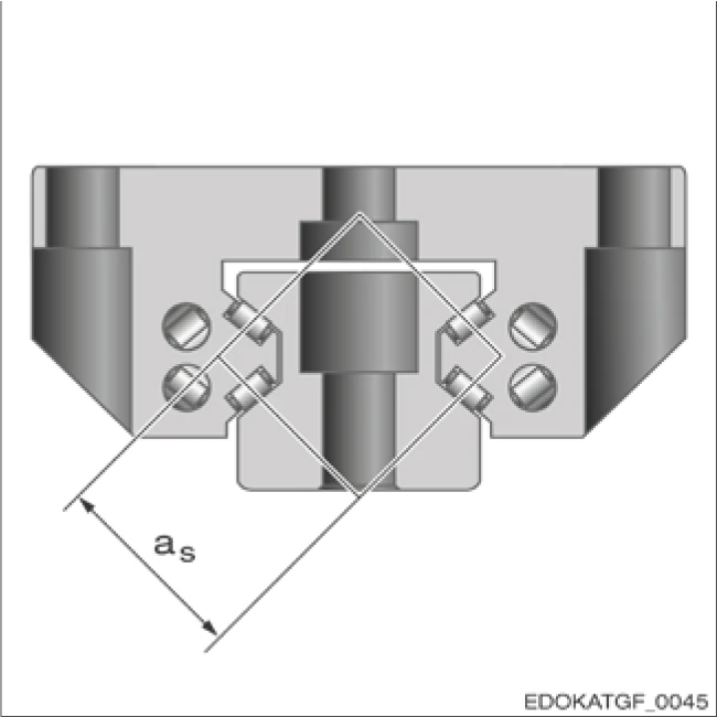
O-geometry with spacing as
Contact Angle
SCHNEEBERGER MONORAIL guideway raceways are arranged at specific angles to enable them to withstand forces from different directions. The contact angle α is defined according to DIN ISO 14728 as the angle between the direction of force acting on the guideway and the contact line.
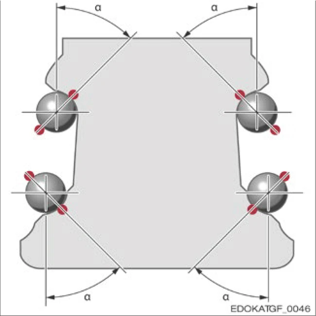
Contact angle of the rolling element with the guide rail
Contact angle parameter:
SCHNEEBERGER Contact Angle
All SCHNEEBERGER MONORAIL guideways have a contact angle of α = 45°, enabling them to simultaneously withstand high load forces from all directions.
1.2.4 Materials
SCHNEEBERGER MONORAIL guideway rails and carriages use high-grade tool steel and various high-grade plastics as materials. Non-ferrous metals and aluminum are used for some accessories.
| Component | Material |
|---|---|
| Guide rail | Ball bearing steel, raceway or entire rail hardened |
| Carriage body | Ball bearing steel, body fully hardened |
| Rolling elements | Ball bearing steel, hardened |
| End plate | PA, injection molded |
| Recirculating unit | POM and polyamide, injection molded |
| Additional wiper | NBR or FPM (Viton) for sealing lips, stainless steel for carrier plate |
| Metal scraper | Stainless steel, corrosion-resistant |
| Reading head | Stainless steel, corrosion-resistant |
1.2.5 Hardening Process
To achieve a sufficiently high load carrying capacity and long service life, in the case of profile rail guideways the surfaces in contact with the rolling element must exhibit a high level of surface hardness. For this purpose, in the case of guide rails and carriages either the rolling element tracks alone or the complete guide rail and the complete carriage body are hardened.
Guide rails
Both guide rails with inductively hardened tracks and through hardened guide rails are offered by SCHNEEBERGER. As well as achieving sufficient load carrying capacity, a hard surface of the guide rails offers the following advantages compared with a supple surface, depending on the application:
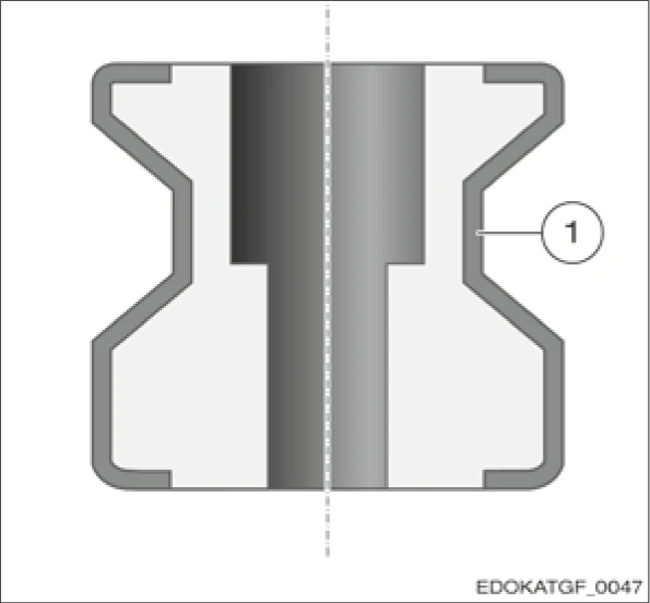
Inductively hardened guide rail with hardness zone (1) based on the example of an MR guide rail
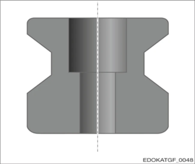
Fully hardened guide rail based on the example of an MR guide rail
- Long service life of wipers
- Surface can be used as a running surface for protective covers (only fully hardened guide rails)
- Protection of the guide rail against incoming swarf (only fully hardened guide rails)
Carriage
The steel bodies of the carriages are the critical element in achieving a long service life with a constant level of precision throughout the entire service life. To maintain these demanding requirements throughout the entire period of operation, even under extreme loads without plastic deformation of the carriage, SCHNEEBERGER uses high-grade roller bearing steel for all of its products. Not only the running surfaces but the complete cross-section of the carriage is hardened with this. Even when subjected to loads exceeding their recommended levels, SCHNEEBERGER carriages retain their factory-set characteristics as in principle no plastic deformation can occur.
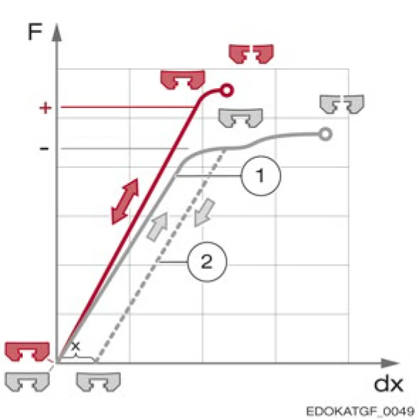
Force F is applied against deformation dx up to breaking point. In case of excessive loading an inductively hardened carriage is subject to plastic deformation, deformation x continues to occur.
Legend: 1 Loaded 2 Unloaded red = fully hardened grey = inductively hardened
Advantages of through hardened carriages:
- A high level of dimensional stability of the carriage body throughout its entire period of operation
- No plastic deformation of the carriage in case of overloading or a crash
- No undefined geometry errors and preload losses
- High level of force absorption up to breaking point
- Ground locating surfaces in the carriage cannot be damaged or scratched during transportation, storage, installation and commissioning