Guide rail types mainly differ in their mounting method, which also determines the closure options for fixing holes. In addition, there are different fixing hole spacings and hardness characteristics. This chapter provides an overview of MONORAIL MR roller and MONORAIL BM/BZ ball types, as well as detailed criteria for guide rail selection.
4.3.1 Guide Rail Types Overview
Guide rail types mainly differ in their mounting method, which also determines the closure options for fixing holes. In addition, there are different fixing hole spacings and hardness characteristics. The following table provides an overview of MONORAIL MR roller and MONORAIL BM/BZ ball types. For available sizes, please refer to the SCHNEEBERGER MONORAIL and AMS product catalog.
MR Guide Rail Product Overview
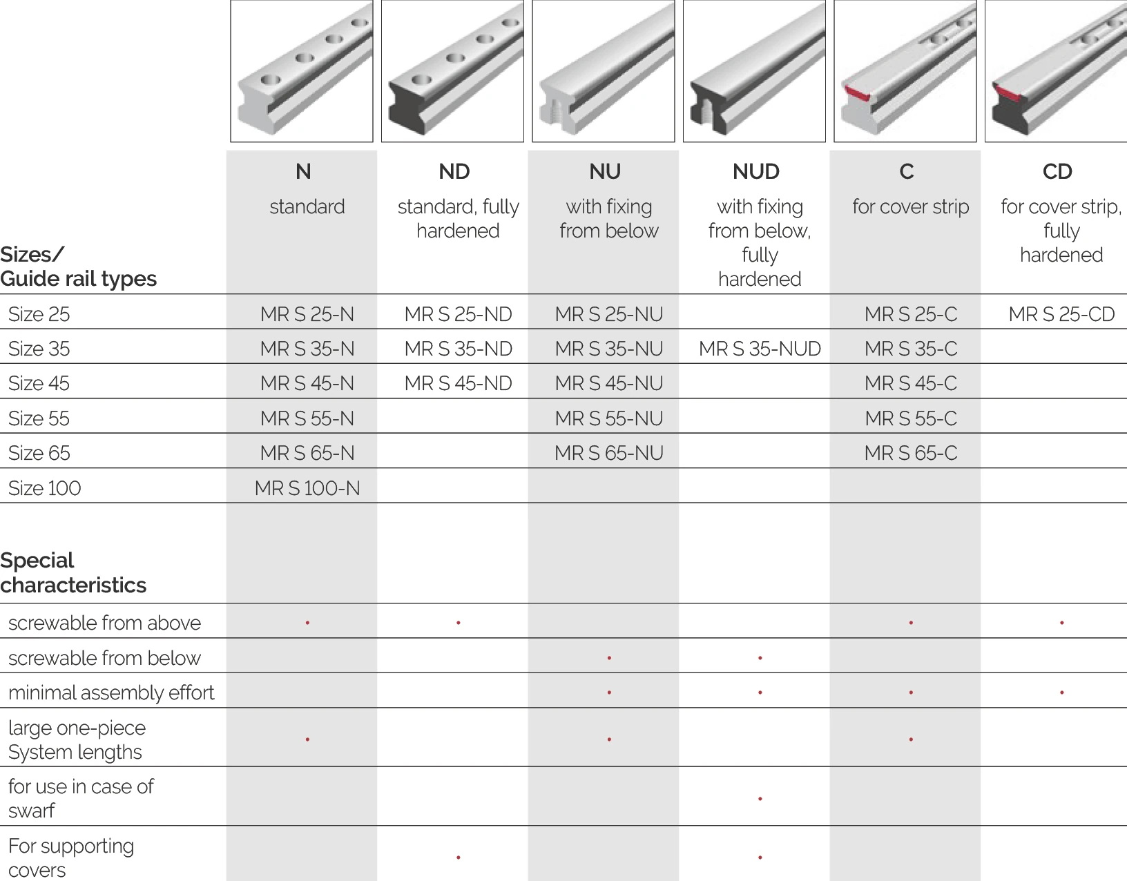
| Size / Guide Rail Type | ||||||
|---|---|---|---|---|---|---|
| N Standard | ND Standard Fully hardened | NU Bottom mounting | NUD Bottom mounting Fully hardened | C Cover strip | CD Cover strip Fully hardened | |
| Size 25 | MR S 25-N | MR S 25-ND | MR S 25-NU | MR S 25-C | MR S 25-CD | |
| Size 35 | MR S 35-N | MR S 35-ND | MR S 35-NU | MR S 35-NUD | MR S 35-C | |
| Size 45 | MR S 45-N | MR S 45-ND | MR S 45-NU | MR S 45-C | ||
| Size 55 | MR S 55-N | MR S 55-NU | MR S 55-C | |||
| Size 65 | MR S 65-N | MR S 65-NU | MR S 65-C | |||
| Size 100 | MR S 100-N | |||||
| Special Characteristics | ||||||
| Fixing from above | ● | ● | ● | ● | ||
| Fixing from below | ● | ● | ||||
| Minimum assembly work | ● | ● | ● | ● | ||
| Large monolithic system length | ● | ● | ● | |||
| For chip environment | ● | |||||
| For supporting cover strips | ● | ● | ||||
BM Guide Rail Product Overview
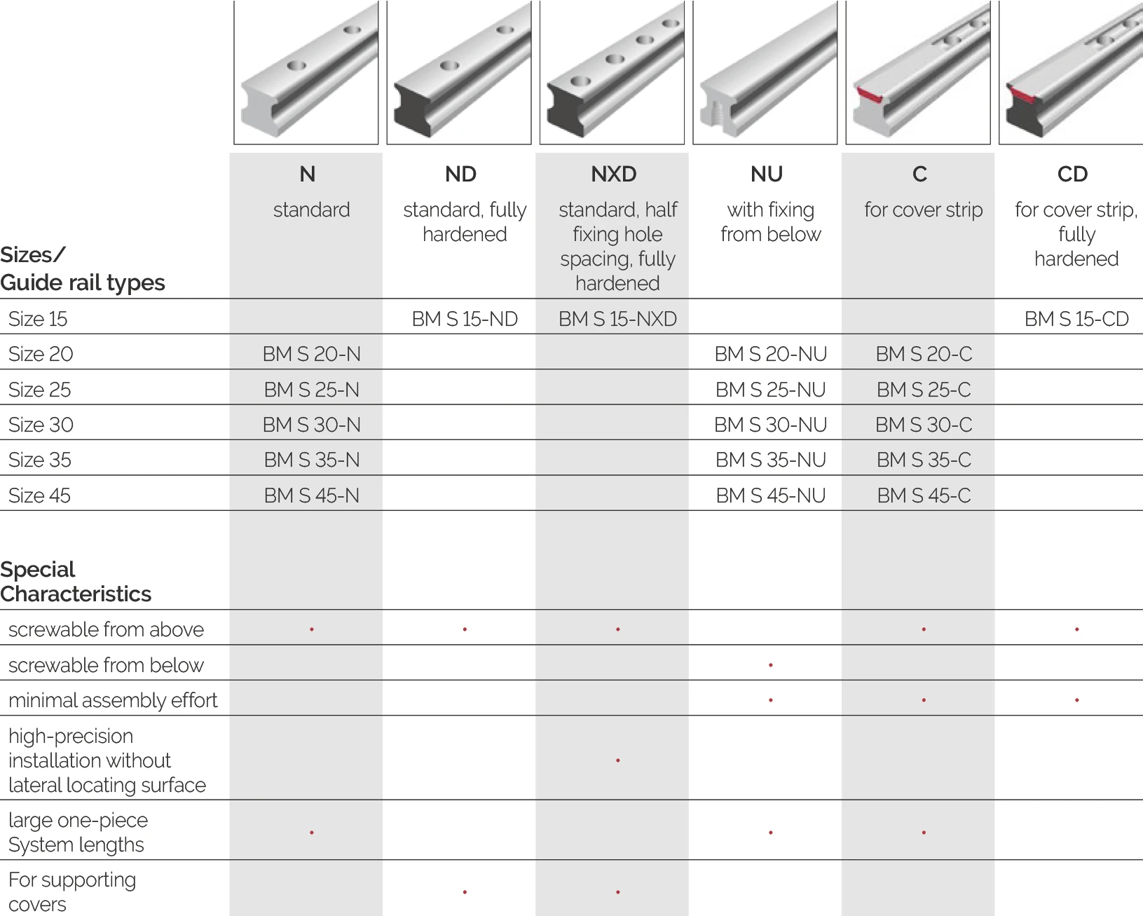
| Size / Guide Rail Type | ||||||
|---|---|---|---|---|---|---|
| N Standard | ND Standard Fully hardened | NXD Standard Half hole spacing Fully hardened | NU Bottom mounting | C Cover strip | CD Cover strip Fully hardened | |
| Size 15 | BM S 15-ND | BM S 15-NXD | BM S 15-CD | |||
| Size 20 | BM S 20-N | BM S 20-NU | BM S 20-C | |||
| Size 25 | BM S 25-N | BM S 25-NU | BM S 25-C | |||
| Size 30 | BM S 30-N | BM S 30-NU | BM S 30-C | |||
| Size 35 | BM S 35-N | BM S 35-NU | BM S 35-C | |||
| Size 45 | BM S 45-N | BM S 45-NU | BM S 45-C | |||
| Special Characteristics | ||||||
| Fixing from above | ● | ● | ● | ● | ● | |
| Fixing from below | ● | |||||
| Minimum assembly work | ● | ● | ● | |||
| High precision mounting without lateral datum surface | ● | |||||
| Large monolithic system length | ● | ● | ● | |||
| For supporting cover strips | ● | ● | ||||
Legend
- N: Standard guide rail
- D: Fully hardened/densified version
- U: With bottom mounting capability
- C: Cover strip version
- ●: This model has this characteristic
4.3.2 Guide Rail Selection Criteria
Mounting Method
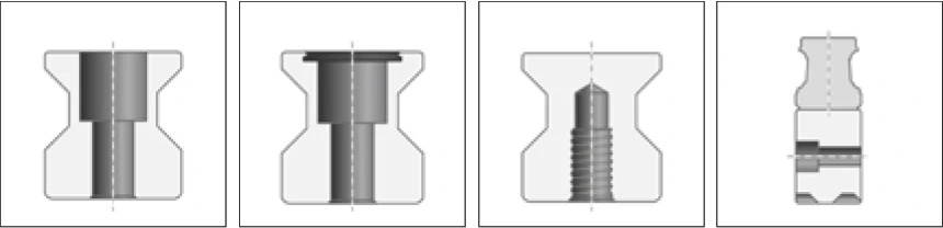
There are two main mounting methods for guide rails. Standard guide rails -N- and cover strip guide rails -C- have continuous fixing holes for mounting from above. N-type guide rail fixing holes can be closed with plastic plugs, brass plugs or steel plugs.
There are also guide rails with threaded fixing holes on the bottom for mounting from below. These guide rails are marked with the -NU- suffix.
The -D- suffix in the model description indicates fully hardened guide rails, -X- indicates rack guide rails for ball bearings (BZ).
| Standard Guide Rails | Special Guide Rails | |||
|---|---|---|---|---|
| Model/Mounting Method | N, ND | C, CD | NU, NUD | NX (BZ) |
| Fixing from above | ● | ● | ||
| Fixing from below | ● | |||
| Fixing from side | ● | |||
Note: ● = Applicable
Side mounting represents the fourth variant, used for the MONORAIL BZ rack system. Because these lateral fixing holes are not located inside the carriage's area of movement, closing them is not essential (plastic plugs BRK can be used if required). The fixing holes for the connecting screws between guide rail and rack are closed at the factory with plastic plugs in the standard design.
Standard guide rail lengths
The standard guide rail lengths for MONORAIL MR and BM are:
L3 = n · L4 − 2 mm
for MONORAIL BZ:
L3 = n · L4
L3 rail length (mm) n = 3, 4, 5… L4 fixing hole pitch (mm)
Guide rails in special lengths
In case of deviations from the standard guide rail lengths set out above, the guide rail length for MONORAIL MR and BM can be calculated using the following formula:
L3 = n · L4 + L5 + L10
L3 rail length n = 3, 4, 5… L4 fixing hole division L5 initial fixing hole spacing L10 end fixing hole spacing (all mm)
In so doing, the following values should be observed for the initial fixing hole spacing L5 and the end fixing hole spacing L10:
L5max, L10max = L4 − (F2/2 + 1 mm)
L5min, L10min = F2/2 + 1 mm
F2 counterbore diameter (mm)
In the case of MONORAIL BZ, the following set values apply for L5 and L10:
L5 = L10 = L4/2
Surface hardness
As standard the side surfaces and tracks of the MONORAIL guide rails are inductively hardened. These guide rails are recommended for normal applications, for large-scale system lengths and if fixing holes need to be incorporated into the guide rail retrospectively, e.g. for pins or for fastening bellows.
In the event that a hardened guide rail upper surface is required, e.g. to support shoes for covers or because the guide rails are being used in an open machining area, through hardened variants are also available. In ND, NUD and CD types, the "D" stands for through harDened.
Guide rail cover
Depending on the type of guide rail, the guide rail fixing holes can be closed in different ways. For this purpose SCHNEEBERGER offers a variety of components for each specific application. The following tables give an overview of the variants on offer and their specific characteristics.

| Guide rail type / order code | U-type rail* | Plastic plugs | Brass plugs | Steel plugs | Cover strip |
|---|---|---|---|---|---|
| MONORAIL MR | ● | MRK | MRS | MRZ | MAC |
| MONORAIL BM | ● | BRK | BRS | — | BAC |
| MONORAIL BZ | — | BRK | — | — | — |
| Characteristic | U-type rail | Plastic plugs | Brass plugs | Steel plugs | Cover strip |
|---|---|---|---|---|---|
| Cost: low | ● | ● | |||
| Cost: medium | ● | ||||
| Cost: high | ● | ● | |||
| Installation effort: low | ● | ● | |||
| Installation effort: medium | ● | ● | |||
| Installation effort: high | ● | ||||
| Space required at rail end | ● | ||||
| Reusable | ● | ||||
| High mechanical load capacity | ● | ● | ● | ||
| Operating conditions: liquids | ● | ● | ● | ● | |
| Operating conditions: fine dust | ● | ● | ● | ● | |
| Operating conditions: coarse swarf | ● | ● | ● | ● | |
| Operating conditions: hot particles | ● | ● | ● | ● | |
| Ease of removal: medium | ● | ||||
| Ease of removal: good | ● | ||||
| Ease of removal: very good | ● | ● |
● = applicable * U-type rail = fastening from below, no rail cover required