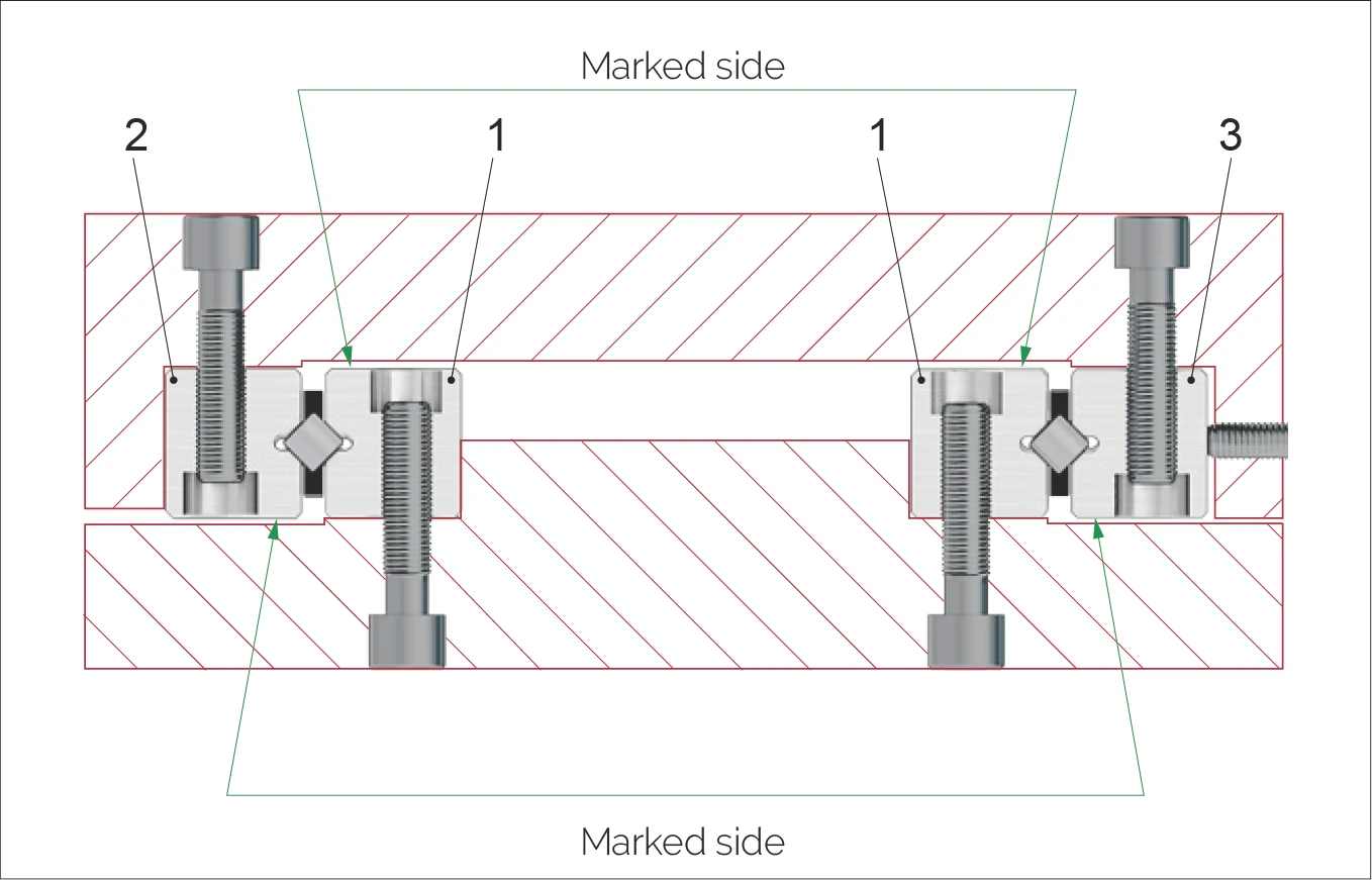
Linear guideway installation cross-section - marked side indication
Linear guideways
With careful, clean preparation and a step by step approach, by adopting a rational procedure you will achieve a perfect guide system.
The following installation instructions apply by analogy for all types of SCHNEEBERGER linear guideways.
Preparation
- To guarantee a perfect support for the guide rails, any remaining burrs or ridges are to be removed with a fine whetstone.
- Before installation, the linear guideways and supporting surfaces should be cleaned. By means of a subsequent light lubrication they will be protected from any consequential damage.
- The marked side of the guide rail may not be used as a supporting surface!
Due to the bore hole tolerances of the rails, the fastening holes in the supporting surfaces should be drilled according to the holes in the linear guideways. By using fastening screws with a thin shaft, differences in hole spacings can also be evened out (see chapter 5).
Install fixed pair of linear guideways
The fixed pair of linear guideways (1) is pressed against the supports using an appropriate clamping element and the fastening screws are tightened (use a torque wrench! For tightening torque see chapter 13.5).
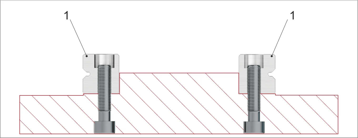
Installation step for fixing one pair of linear guideways (1)
Check parallelism
Check parallelism ΔA and ΔP. The parallelisms measured must fall within the tolerances of the linear guideway (see chapter 7.1).
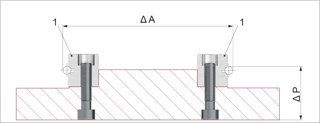
Check parallelism ΔA (horizontal distance) and ΔP (vertical height difference)
Install opposing fixed rail
Install the fixed rail (2) of the opposing pair.
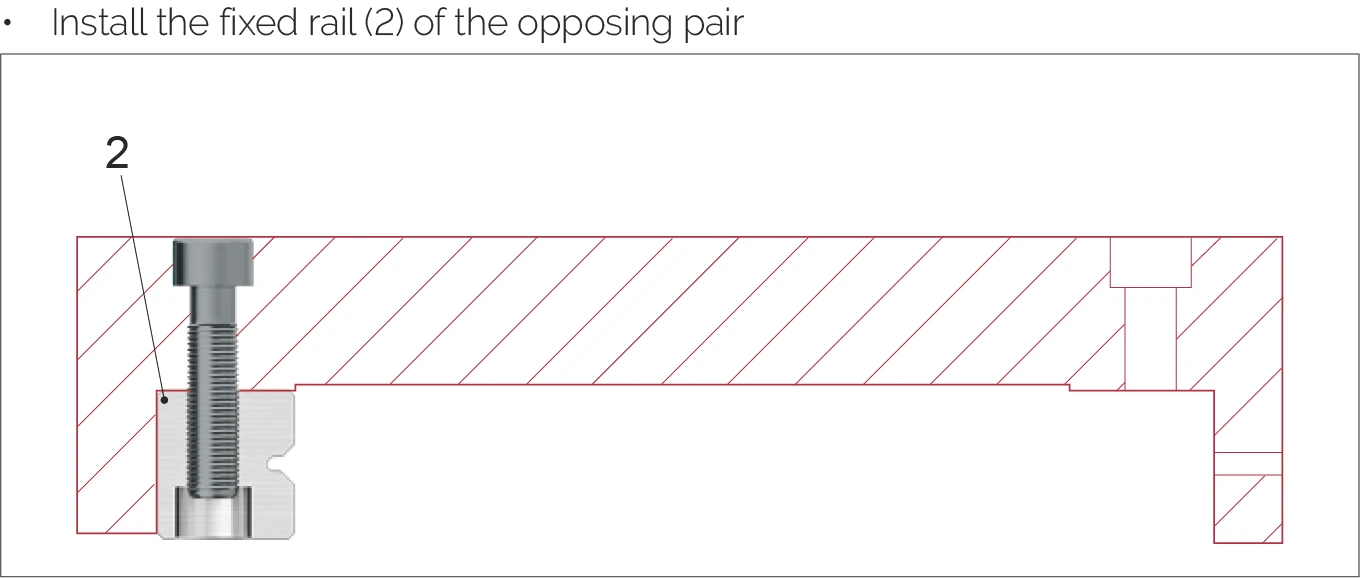
Install the fixed rail (2) of the opposing pair
Install rail and lubricate
Install the rail (3) and in so doing only lightly tighten the fastening screws. Perform lubrication (see chapter 13.8).
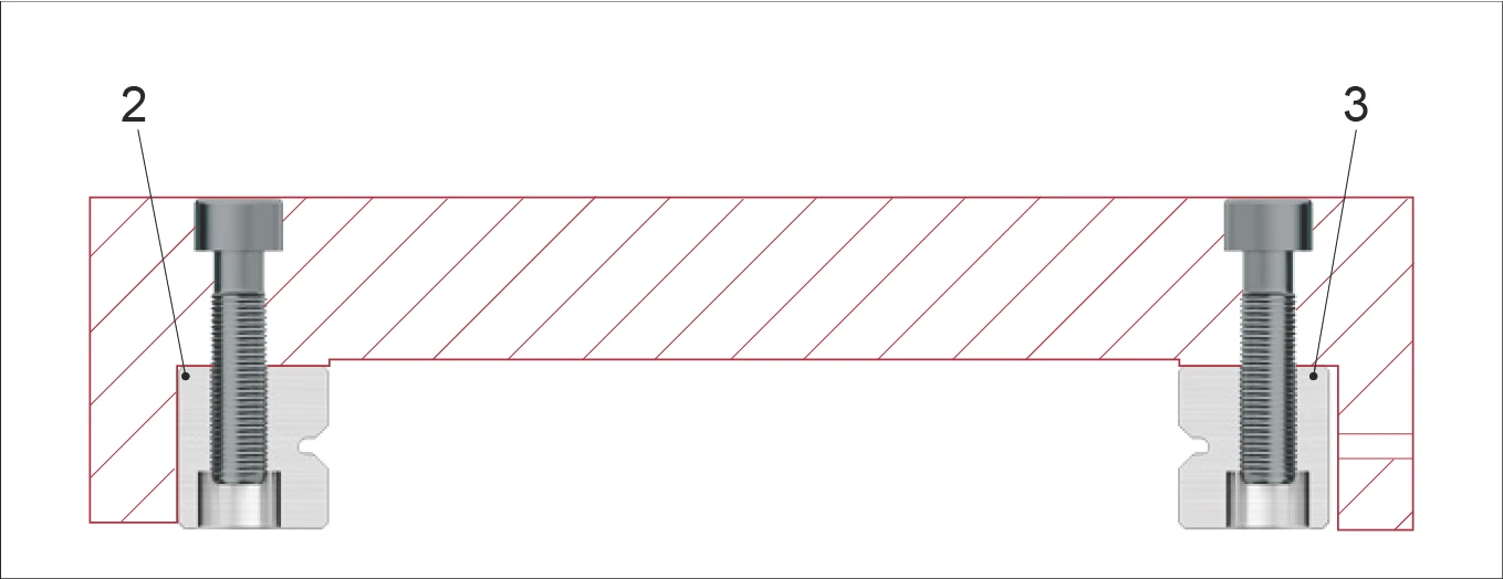
Install the rail (3) with lightly tightened fastening screws, then lubricate
Insert and center cages
Insert and center the cages (4). After that the linear bearings must be preloaded (please refer to the following page).
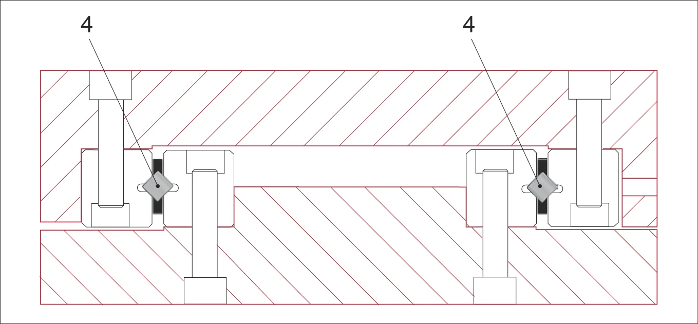
Insert and center the cages (4), ready for preloading
Set and preload linear guideway
Set and/or preload the linear guideway with zero-backlash (see chapter 13.5).
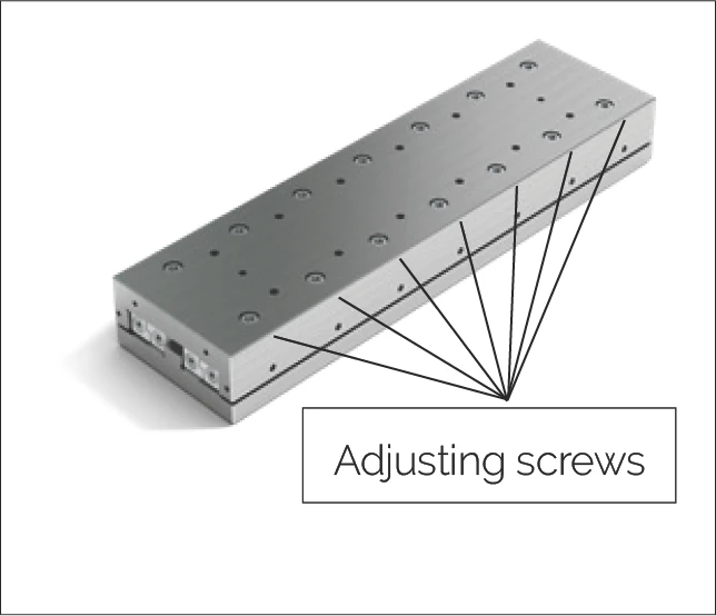
Set and preload the linear guideway using the adjusting screws
Apply preload sequence
Application of the preload using the adjusting screws should be carried out from the centre of the rail outwards using the following steps (the sequence can be worked out from the figures):
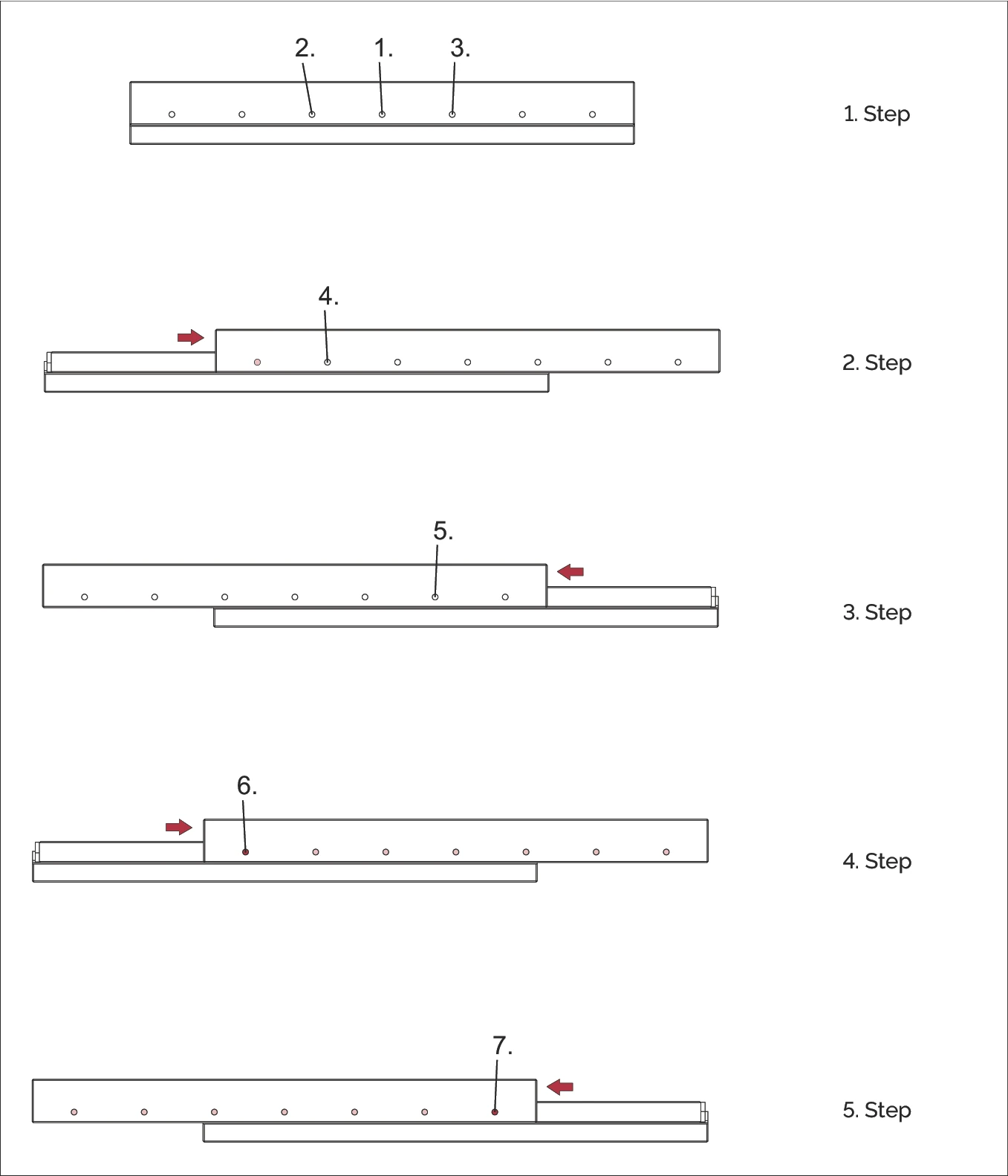
Five steps for applying preload from the centre of the rail outwards
Tighten screws and install end pieces
Tighten the fastening screws for the rail (3) and install the end pieces.
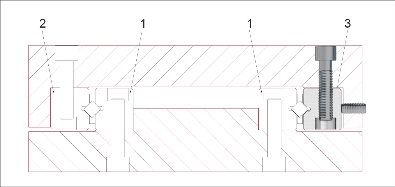
Tighten rail fastening screws and install the end pieces
Chapter 14: Order Descriptions
Examples for linear guideways
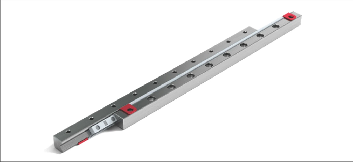
Example 1 - set consists of
| Component | Quantity | Type and size | Length in mm | Options |
|---|---|---|---|---|
| Guide rails | 4 | RNG 6 | -300 | -RF-SSQ-KS |
| Cage | 2 | KBS 6 x 20* | - | -RF |
* corresponds to the number of rolling elements
Set RNG 6-300-RF-SSQ-KS; KBS 6x20-RF consisting of:
- 4 pcs. Linear guide RNG 6-300-RF-SSQ-KS
- 2 pcs. Cage KBS 6x20-RF
Example 2 - set consists of
| Component | Quantity | Type and size | Length in mm | Options |
|---|---|---|---|---|
| Guide rails | 2 | R 9 | -800 | - |
| Guide rails | 2 | R 9 | -600 | -EG |
| Cage | 2 | AC 9 x 22* | - | - |
| End pieces | 8 | GC 9 | - | - |
* corresponds to the number of rolling elements
Set R 9-800/600-EG; AC 9x22; GC 9 consisting of:
- 2 pcs. Linear guides R 9-800
- 2 pcs. Linear guides R 9-600-EG
- 2 pcs. Cage AC 9x22
- 8 pcs. End piece GC 9
In the case of cage types HW and SHW, the cage length must be indicated in mm!
e.g. SHW 20 x 155 mm
Example recirculating unit
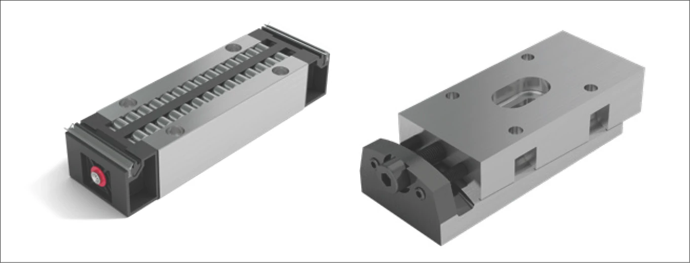
Recirculating unit set composition
| Component | Quantity | Type and size | Options |
|---|---|---|---|
| Recirculating units | 150 | NRT 26111 | -GP |
| Preload wedge | 150 | NRV 26111 | - |