High-quality mounting accessories are essential to achieving the best performance from miniature ball bearings. myonic offers a range of precision accessories matched exactly to the bearing dimensions; All data follow the official product-myonic.com current specification tables.
WSR – Circlips for Shafts 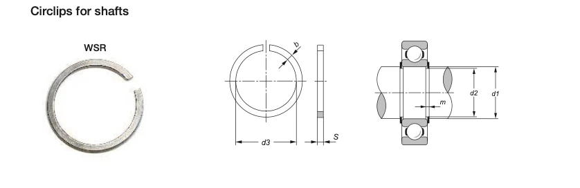
BSR – Circlips for Bores 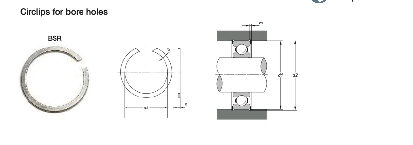
WSR/BSR Series Specification Tables
Material: stainless steel.
| Designation | Shaft / bore diameter Ø d1 | Circlip d3 | Groove | D2 | m | Suitable for ball bearings Suitable for ball bearings | ||
|---|---|---|---|---|---|---|---|---|
| b | s | Ø (mm) | Ø (inch) | |||||
| mm | mm (max/min) | mm (±0.10) | mm | mm | mm | |||
| WSR series (for shafts; d3 is max., s tolerance ±0.015, D2 tolerance -0.05, m tolerance +0.03; the Suitable for ball bearings column gives the Inner diameter) | ||||||||
| WSR 3 | 3 | 2.60 | 0.50 | 0.30 | 2.70 | 0.33 | 3 | .1250 |
| WSR 4 | 4 | 3.60 | 0.50 | 0.30 | 3.70 | 0.33 | 4 | .1562 |
| WSR 5 | 5 | 4.50 | 0.70 | 0.40 | 4.60 | 0.44 | 5 | – |
| WSR 6 | 6 | 5.45 | 0.70 | 0.40 | 5.60 | 0.44 | 6 | .2500 |
| WSR 7 | 7 | 6.45 | 0.70 | 0.40 | 6.60 | 0.44 | 7 | – |
| WSR 8 | 8 | 7.35 | 0.90 | 0.50 | 7.50 | 0.55 | 8 | .3125 |
| WSR 9 | 9 | 8.30 | 0.90 | 0.50 | 8.50 | 0.55 | 9 | – |
| WSR 10 | 10 | 9.25 | 0.90 | 0.50 | 9.50 | 0.55 | 10 | – |
| BSR series (for bores; d3 is min., d2 tolerance +0.05, m tolerance +0.03; for the s tolerance see the BSR thickness tolerance table; the Suitable for ball bearings column gives the Outer diameter) | ||||||||
| BSR 4 | 4 | 4.40 | 0.50 | 0.30 | 4.30 | 0.33 | 4 | .1562 |
| BSR 5 | 5 | 5.45 | 0.50 | 0.30 | 5.30 | 0.33 | 5 | – |
| BSR 6 | 6 | 6.45 | 0.50 | 0.30 | 6.30 | 0.33 | 6 | – |
| BSR 7 | 7 | 7.50 | 0.50 | 0.30 | 7.30 | 0.33 | 7 | – |
| BSR 8 | 8 | 8.60 | 0.70 | 0.40 | 8.40 | 0.44 | 8 | .3125 |
| BSR 9 | 9 | 9.60 | 0.70 | 0.40 | 9.40 | 0.44 | 9 | – |
| BSR 10 | 10 | 10.65 | 0.70 | 0.40 | 10.40 | 0.44 | 10 | – |
| BSR 11 | 11 | 11.65 | 0.70 | 0.40 | 11.40 | 0.44 | 11 | – |
| BSR 12 | 12 | 12.75 | 0.90 | 0.50 | 12.50 | 0.55 | 12 | – |
| BSR 13 | 13 | 13.75 | 0.90 | 0.50 | 13.50 | 0.55 | 13 | – |
| BSR 14 | 14 | 14.80 | 0.90 | 0.50 | 14.50 | 0.55 | 14 | – |
| BSR 15 | 15 | 15.80 | 0.90 | 0.50 | 15.50 | 0.55 | 15 | – |
| BSR 16 | 16 | 16.85 | 0.90 | 0.50 | 16.50 | 0.55 | 16 | – |
| BSR 17 | 17 | 17.85 | 0.90 | 0.50 | 17.50 | 0.55 | 17 | – |
| BSR 19 | 19 | 20.00 | 1.10 | 0.60 | 19.60 | 0.66 | 19 | .7500 |
BSR Thickness s Tolerance
| Thickness (mm) | Tolerance (mm) |
|---|---|
| < 0.6 | ± 0.015 |
| < 0.8 | ± 0.02 |
FS – Precision Spring Washers 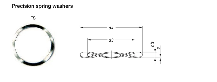
FS Series Specification Table
Used to eliminate bearing clearance and provide a stable preload. Material: stainless steel.
| Designation | h+s (±0.05) | s* | d3 | d4 | Suitable for ball bearings with | |||
|---|---|---|---|---|---|---|---|---|
| Inner diameter | Outer diameter | |||||||
| mm | mm | mm | mm | mm | inch | mm | inch | |
| FS 1.5 X 3 | 0.40 | 0.08 | 1.60 | 2.90 | – | – | 3 | – |
| FS 2 X 3.5 | 0.45 | 0.08 | 2.15 | 3.10 | 2 | – | – | .1250 |
| FS 2.5 X 4 | 0.50 | 0.08 | 2.70 | 3.80 | 2.5 | – | 4 | .1562 |
| FS 3 X 4.5 | 0.50 | 0.10 | 3.20 | 4.30 | 3 | .1250 | – | – |
| FS 3.5 X 5 | 0.55 | 0.10 | 3.70 | 4.80 | – | – | 5 | – |
| FS 4 X 6 | 0.65 | 0.12 | 4.20 | 5.75 | 4 | .1562 | 6 | – |
| FS 4.5 X 6.35 | 0.60 | 0.12 | 4.80 | 6.10 | – | .1875 | – | .2500 |
| FS 5 X 7 | 0.65 | 0.12 | 5.20 | 6.75 | 5 | – | 7 | – |
| FS 6 X 8 | 0.70 | 0.15 | 6.20 | 7.80 | 6 | – | 8 | .3125 |
| FS 7 X 9 | 0.90 | 0.15 | 7.20 | 8.70 | 7 | – | 9 | – |
| FS 8 X 10 | 0.85 | 0.18 | 8.20 | 9.70 | 8 | .3125 | 10 | – |
| FS 9 X 11 | 1.15 | 0.18 | 9.20 | 10.70 | 9 | – | 11 | – |
| FS 10 X 12 | 1.05 | 0.20 | 10.20 | 11.70 | 10 | – | 12 | – |
| FS 11 X 13 | 1.30 | 0.20 | 11.20 | 12.70 | – | – | 13 | – |
| FS 12 X 14 | 1.30 | 0.22 | 12.20 | 13.70 | – | – | 14 | – |
| FS 13 X 15 | 1.30 | 0.22 | 13.20 | 14.70 | – | – | 15 | – |
| FS 14 X 16 | 1.55 | 0.25 | 14.20 | 15.65 | – | – | 16 | – |
| FS 15 X 17 | 1.55 | 0.25 | 15.20 | 16.65 | – | – | 17 | – |
| FS 16 X 19 | 2.15 | 0.30 | 16.20 | 18.55 | – | – | 19 | .7500 |
FS Thickness s* Tolerance
| Thickness (mm) | Tolerance (mm) |
|---|---|
| < 0.2 | ± 0.01 |
| < 0.3 | ± 0.012 |
| < 0.4 | ± 0.015 |
PS – Precision Shims 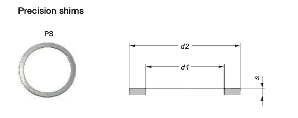
PS Series Specification Table
Used to fill tolerance gaps. Specify the thickness s when ordering (e.g. PS 8 X 10 X 0.18). Material: stainless steel.
The official catalog lists 2–3 thickness variants per designation; they are combined here in a single column separated by “/”.
| Designation | Available thickness s* | d1 | d2 | Suitable for ball bearings with | |||
|---|---|---|---|---|---|---|---|
| Inner diameter | Outer diameter | ||||||
| mm | mm | mm | mm | inch | mm | inch | |
| PS 1.5 X 3 | 0.08 / 0.10 | 1.68 | 2.97 | – | – | 3 | – |
| PS 2 X 3.5 | 0.08 / 0.10 | 2.25 | 3.20 | 2 | – | – | .1250 |
| PS 2.5 X 4 | 0.08 / 0.10 | 2.80 | 3.90 | 2.5 | – | 4 | .1562 |
| PS 3 X 4.5 | 0.08 / 0.10 / 0.12 | 3.30 | 4.40 | 3 | .1250 | – | – |
| PS 3.5 X 5 | 0.10 / 0.12 | 3.80 | 4.90 | – | – | 5 | – |
| PS 4 X 6 | 0.10 / 0.12 / 0.15 | 4.30 | 5.85 | 4 | .1562 | 6 | – |
| PS 4.5 X 6.35 | 0.10 / 0.12 / 0.15 | 4.90 | 6.20 | – | .1875 | – | .2500 |
| PS 5 X 7 | 0.12 / 0.15 | 5.30 | 6.85 | 5 | – | 7 | – |
| PS 6 X 8 | 0.12 / 0.15 / 0.18 | 6.30 | 7.85 | 6 | – | 8 | .3125 |
| PS 7 X 9 | 0.15 / 0.18 | 7.30 | 8.80 | 7 | – | 9 | – |
| PS 8 X 10 | 0.15 / 0.18 / 0.20 | 8.30 | 9.80 | 8 | .3125 | 10 | – |
| PS 9 X 11 | 0.18 / 0.20 | 9.30 | 10.80 | 9 | – | 11 | – |
| PS 10 X 12 | 0.18 / 0.20 / 0.22 | 10.30 | 11.80 | 10 | – | 12 | – |
| PS 11 X 13 | 0.20 / 0.22 | 11.30 | 12.80 | – | – | 13 | – |
| PS 12 X 14 | 0.20 / 0.22 / 0.25 | 12.30 | 13.80 | – | – | 14 | – |
| PS 13 X 15 | 0.22 / 0.25 | 13.30 | 14.80 | – | – | 15 | – |
| PS 14 X 16 | 0.22 / 0.25 / 0.30 | 14.35 | 15.80 | – | – | 16 | – |
| PS 15 X 17 | 0.25 / 0.30 | 15.35 | 16.80 | – | – | 17 | – |
| PS 16 X 19 | 0.30 / 0.35 | 16.40 | 18.80 | – | – | 19 | .7500 |
PS Thickness s* Tolerance
| Thickness (mm) | Tolerance (mm) |
|---|---|
| 0.05 – 0.15 | ± 0.008 |
| 0.15 – 0.20 | ± 0.010 |
| 0.20 – 0.30 | ± 0.012 |
| 0.30 – 0.40 | ± 0.015 |
| 0.40 – 0.60 | ± 0.020 |
| 0.60 – 0.80 | ± 0.025 |