Rail Type AMSABS 3L S 35
| AMSABS 3L S 35-N |
 |
| Standard type (top mounting) |
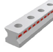
AMSABS 3L Features: Designed specifically for long-axis measurement, multiple rail segments can be connected to achieve measuring lengths exceeding 6m. The rail junction uses a special design allowing the reading head to pass smoothly through connection points.
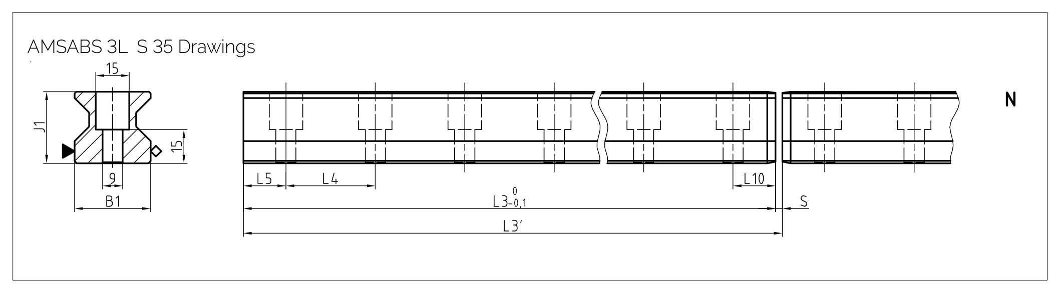
Rail Dimensional Drawing AMSABS 3L S 35
Rail Specifications AMSABS 3L S 35
| Parameter | AMSABS 3L S 35-N |
| Rail width B1 (mm) | 34 |
| Rail height J1 (mm) | 31.95 |
| Maximum single segment length L3 (mm) | 2 999.5 |
| System length L3' (mm) | 3 000 |
| Connection gap S (mm) | 0.5 |
| Mounting hole pitch L4 (mm) | 40 |
| First/last hole position L5/L10 (mm) | 19.75 |
| Unit weight (kg/m) | 6.5 |
Carriage Types AMSABS 3L W 35
| W 35-A | W 35-B | W 35-C | W 35-D |
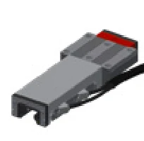 | 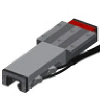 | 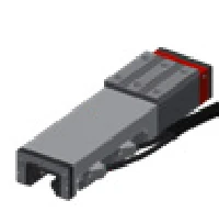 | 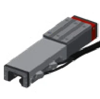 |
Standard type
High load | Standard long type
High load | High-narrow type
High load | High-narrow long type
High load |
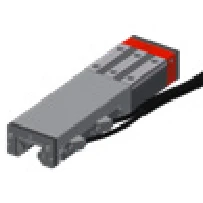
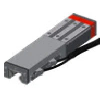
| W 35-E | W 35-F | W 35-G |
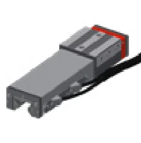 |  |  |
High-narrow lateral mount
High load | Flat type
Medium load | Flat long type
Medium load |
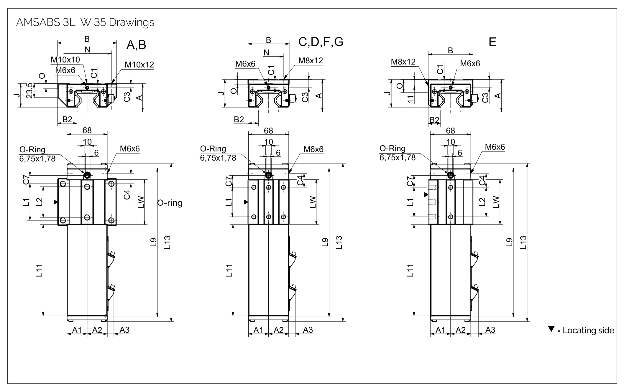
Carriage Dimensional Drawing AMSABS 3L W 35
Carriage Specifications AMSABS 3L W 35
| Parameter | AMSABS 3L W 35-A | AMSABS 3L W 35-B | AMSABS 3L W 35-C | AMSABS 3L W 35-D | AMSABS 3L W 35-E | AMSABS 3L W 35-F | AMSABS 3L W 35-G |
| System height A (mm) | 48 | 48 | 55 | 55 | 55 | 48 | 48 |
| Housing Half Width, Opposite Side A1 (mm) | 34 | 34 | 34 | 34 | 34 | 34 | 34 |
| Housing Half Width, Reading Head Side A2 (mm) | 34 | 34 | 34 | 34 | 34 | 34 | 34 |
| Reading head projection A3 (mm) | 11.5 | 11.5 | 11.5 | 11.5 | 11.5 | 11.5 | 11.5 |
| Carriage width B (mm) | 100 | 100 | 70 | 70 | 76 | 70 | 70 |
| Locating face distance B2 (mm) | 33 | 33 | 18 | 18 | 21 | 18 | 18 |
| Front-face center lubrication port position C1 (mm) | 7 | 7 | 7 | 7 | 13.5/14 | 6.5/7 | 6.5/7 |
| Side lubrication port position C3 (mm) | 7 | 7 | 14 | 14 | 14 | 7 | 7 |
| Side lubrication port position (second) C4 (mm) | 17 | 30.5 | 23 | 25.5 | 23 | 23 | 25.5 |
| Top lubrication port position C7 (mm) | 14 | 27.5 | 20 | 22.5 | 20 | 20 | 22.5 |
| Carriage height J (mm) | 40 | 40 | 47 | 47 | 47 | 40 | 40 |
| Outer mounting hole pitch L1 (mm) | 62 | 62 | 50 | 72 | 50 | 50 | 72 |
| Inner mounting hole pitch L2 (mm) | 52 | 52 | — | — | 50 | — | — |
| Carriage length with housing L9 (mm) | 252.5 | 279.5 | 252.5 | 279.5 | 252.5 | 252.5 | 279.5 |
| Housing length L11 (mm) | 156.5 | 156.5 | 156.5 | 156.5 | 156.5 | 156.5 | 156.5 |
| Measuring carriage total length L13 (mm) | 269 | 296 | 269 | 296 | 269 | 269 | 296 |
| Carriage body inner length Lw (mm) | 76 | 103 | 76 | 103 | 76 | 76 | 103 |
| Lateral mounting hole pitch N (mm) | 82 | 82 | 50 | 50 | — | 50 | 50 |
| Reference face height O (mm) | 8 | 8 | 8 | 8 | 22 | 8 | 8 |
Load Ratings
| Parameter | AMSABS 3L W 35-A | AMSABS 3L W 35-B | AMSABS 3L W 35-C | AMSABS 3L W 35-D | AMSABS 3L W 35-E | AMSABS 3L W 35-F | AMSABS 3L W 35-G |
| Static Load Capacity C₀ (N) | 93400 | 128500 | 93400 | 128500 | 93400 | 93400 | 128500 |
| Dynamic Load Capacity C₁₀₀ (N) | 52000 | 71500 | 52000 | 71500 | 52000 | 52000 | 71500 |
| Static Cross Moment Capacity M₀Q (Nm) | 2008 | 2762 | 2008 | 2762 | 2008 | 2008 | 2762 |
| Static Longitudinal Moment Capacity M₀L (Nm) | 1189 | 2214 | 1189 | 2214 | 1189 | 1189 | 2214 |
| Dynamic Cross Moment Capacity MQ (Nm) | 1118 | 1537 | 1118 | 1537 | 1118 | 1118 | 1537 |
| Dynamic Longitudinal Moment Capacity ML (Nm) | 662 | 1232 | 662 | 1232 | 662 | 662 | 1232 |
| Carriage Weight (kg) | 2.3 | 3.0 | 2.3 | 2.8 | 2.6 | 2.0 | 2.8 |
* This value differs from the value printed in the manufacturer's catalogue (p.201). The catalogue prints
9344 (C₀) and 71500 (M₀Q) in these cells, which are judged to be typesetting errors by the manufacturer—
the former has one zero fewer than the other types in the same row, the latter is identical to the C₁₀₀ value in the same column. Based on the
specification relationship within the same type group (E corresponds to A, G corresponds to B), this page corrects them to 93400 and 2762.
Verification with the manufacturer before ordering is recommended.
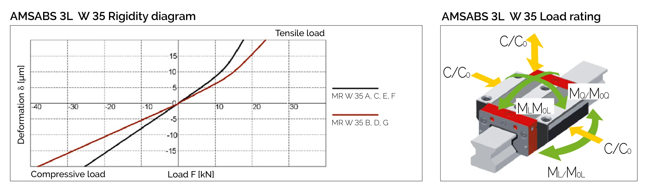
Rigidity Diagram and Load Directions AMSABS 3L W 35
Order Code Examples
Rail Order Code
AMSABS 3L S 35-N-G1-KC-R11-3000-CN-P0
- AMSABS 3L S 35 = AMSABS 3L Rail Size 35
- N = Standard type
- G1 = Very accurate
- KC = Standard straightness
- R11 = Reference side 1
- 3000 = Rail length 3000mm
Carriage Order Code
AMSABS 3L W 35-B-P1-G1-V3-R2-CN-S12-LN-TSH-TS3
- AMSABS 3L W 35 = AMSABS 3L Carriage Size 35
- B = Standard long type carriage
- P1 = Reading head position 1
- G1 = Very accurate
- V3 = High preload
- TSH = SSI interface