4.14.1 Standard Seals
Carriages of SCHNEEBERGER MONORAIL guideways are equipped as standard with double-lip end wipers and two top and bottom longitudinal wipers on each side. These sealing elements provide effective sealing to prevent contaminants from entering and minimize lubricant loss, thereby extending guideway service life.
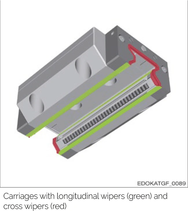
Carriage equipped with longitudinal wipers (green) and end wipers (red)
MONORAIL BM Wiper Variants
MONORAIL BM ball guideways are often used in applications with lower contamination levels but requiring low thrust. Therefore, in addition to standard end wipers, these guideways also offer special low-friction wipers, as well as wiper-free options for cleanroom applications.
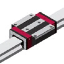
Standard Wiper
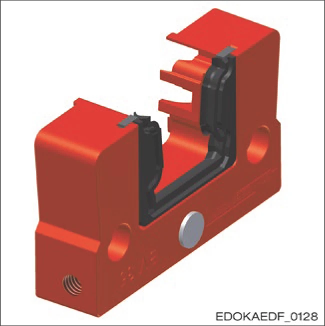
Wiper Type: Standard wiper
Order Code: QN
Application: General industrial environments
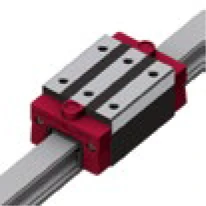
Low-Friction Wiper
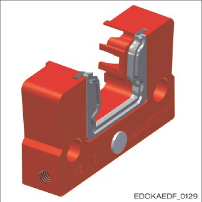
Wiper Type: Low-friction wiper
Order Code: QL
Application: Low contamination environments, low thrust required
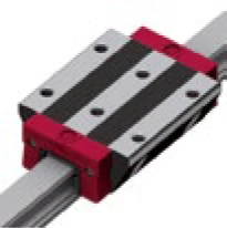
Without End Wipers
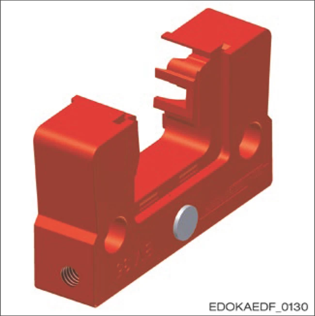
Wiper Type: Without end wipers
Order Code: Q0
Application: Cleanroom environments
Important: Correct sealing system selection is critical for guideway system reliability and service life. Please select the appropriate wiper type according to your specific application conditions.
4.14.2 Additional Wipers
For special operating conditions such as heavy dust accumulation, chip deposits, or coolant environments, SCHNEEBERGER provides additional seals that are installed in front of the carriage to provide additional mechanical protection.
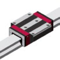
NBR Additional Wipers
NBR (nitrile rubber) additional wipers provide extra protection for carriages in heavily contaminated environments. They consist of a load plate with a very robust single-lip seal installed on it. Due to the flexibility of the wiper, which can be pushed over the guide rail cross-section, it can be retrofitted without removing the carriage from the guide rail.
NBR additional wipers are available for all MR and BM carriage types. Order code is "ZBN xx" for BM carriages and "ZCN xx" for MR carriages, where "xx" represents the size.
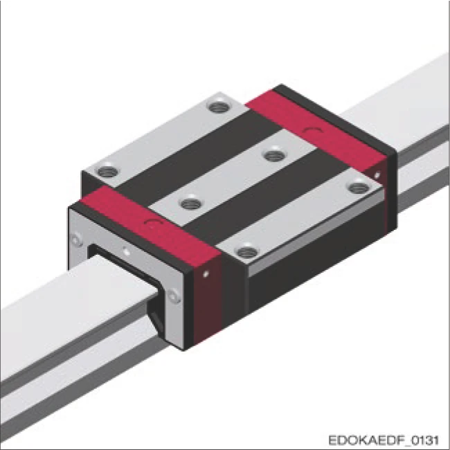
Carriage equipped with NBR additional wiper
Viton Additional Wipers
Similar to NBR wipers, Viton additional wipers provide extra protection for carriages in heavily contaminated environments. However, they are also suitable for applications with corrosive coolants, as Viton® (fluorinated rubber) is chemically resistant and exhibits high temperature resistance. Due to the flexibility of the wiper, which can be pushed over the guide rail cross-section, it can also be retrofitted without removing the carriage from the guide rail.
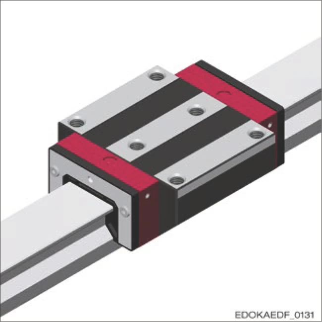
Carriage equipped with Viton additional wiper
Metal Wipers
Metal wipers are made of stainless steel and are used to protect the sealing lips and additional wipers of the carriage from hot chips. Large and loose dirt particles are pushed away and do not get stuck due to the larger radial clearance from the guide rail. Specially adapted types are available for guide rails using the AMS measuring system.
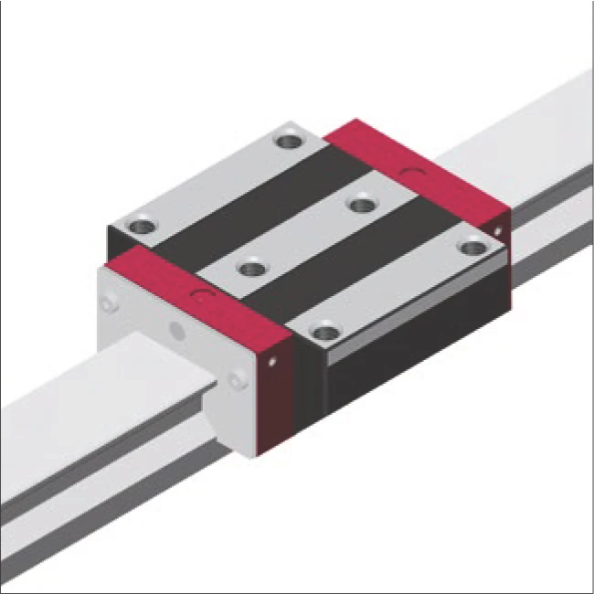
Carriage equipped with metal wiper
Installation Note: Metal wipers and additional wipers can be used in combination. They can also be combined with lubrication plate SPL.
| Size* | MR 25 | MR 35 | MR 45 | MR 55 | MR 65 |
|---|---|---|---|---|---|
| LA | 13 | 20 | 22 | 28 | 35 |
| LZ | 2.5 | 2.5 | 2.5 | 2.5 | 2.5 |
| TE | 8 | 8 | 8 | 8 | 8 |
| TZ | 12 | 10 | 10 | 10 | 10 |
| Size* | BM 20 | BM 25 | BM 30 | BM 35 | BM 45 |
|---|---|---|---|---|---|
| LA | 12 | 12 | 15 | 20 | 22 |
| LZ | 2 | 2.7 | 2.7 | 2.7 | 2.7 |
| TE | 8 | 8 | 8 | 8 | 8 |
| TZ | 10 | 10 | 10 | 10 | 10 |
* Dimensions in mm. LA = extension per fold of the bellows, LZ = compression of the folds in the bellows, TE = thickness of the end plate, TZ = thickness of the adapter plate
4.14.3 Bellows
Bellows are mainly used as an additional form of protection for carriages against dust and splashing water.
They are available in a standard design for MONORAIL MR roller guideways and MONORAIL BM ball guideways. The bellows are made of synthetic fabric coated with plastic on both sides. They extend over the entire length of the guide rail, and their cross-section matches the corresponding end plates on the carriage.
For special applications, e.g. in laser cutting or welding systems, a version in heat-resistant material is also available on request.
The bellows are fastened simply using special plates, which are screwed on to the guide rail ends or to the carriage front plate. The bellows are fastened by two rivets to both the adapter plate and the end plate.
Retro-fitting is only recommended for inductively hardened guide rails, as holes need to be drilled into the end of the guide rail for attaching the end plate.
Order code is "FBB" for all BM carriages sizes 20-45, and "FBM" for all MR carriages sizes 25-65.
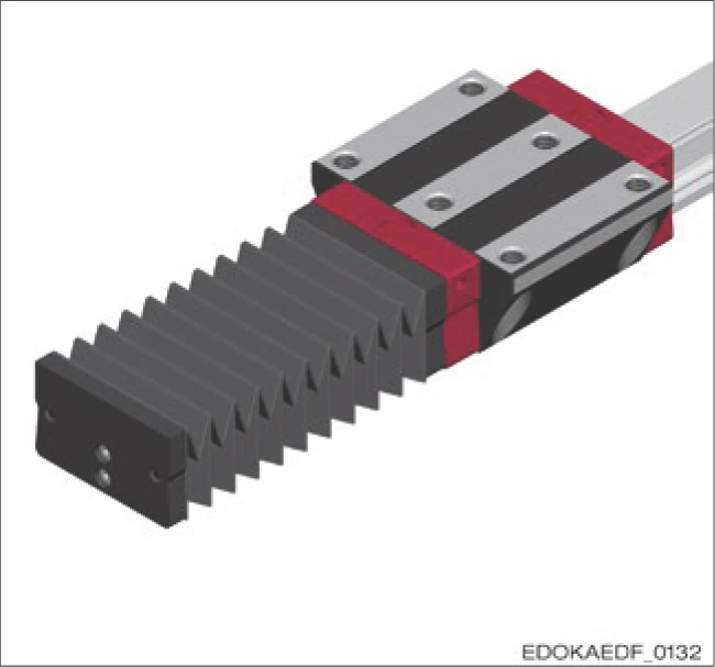
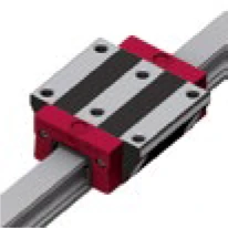
Carriage equipped with bellows
Caution
Component damage due to improper structure
- When using bellows, it is important to ensure that due to any vacuum that may occur during movement, dirt is not drawn under the bellows.
Calculating Length
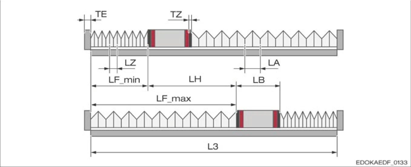
Guide rail length for one carriage
Length for one guide rail with one carriage:
| Symbol | Description |
|---|---|
| LB | Total length with adapter plate |
| LH | Stroke |
| LF_min | Bellows compression |
| LF_max | Bellows extension length |
| L3 | Guide rail length |
| Size* | MR 25, FBM 25 | MR 35, FBM 35 | MR 45, FBM 45 | MR 55, FBM 55 | MR 65, FBM 65 |
|---|---|---|---|---|---|
| BE | 47 | 68 | 84 | 98 | 123 |
| BZ | 47 | 68 | 84 | 98 | 123 |
| HE | 30 | 40 | 50 | 57 | 76 |
| HZ | 29 | 39.5 | 49.5 | 56.5 | 75.5 |
| H1 | 10 | 12 | 15 | 20 | 22 |
| H2 | 10.5 | 14 | 17 | 20 | 25 |
| S × GE | M4 × 5 | M4 × 5 | M6 × 8.5 | M6 × 8.5 | M6 × 8.5 |
| Size* | BM 20, FBB 20 | BM 25, FBB 25 | BM 30, FBB 30 | BM 35, FBB 35 | BM 45, FBB 45 |
|---|---|---|---|---|---|
| BE | 43 | 47 | 58.5 | 68 | 84 |
| BZ | 43 | 47 | 58.5 | 68 | 84 |
| HE | 25 | 30 | 35 | 40 | 50 |
| HZ | 25 | 30 | 35 | 39.5 | 49.5 |
| H1 | 6.5 | 8 | 8 | 10.5 | 13.5 |
| H2 | 8.5 | 10 | 12 | 13 | 16.7 |
| S × GE | M3 × 12 | M4 × 8 | M4 × 8 | M4 × 8 | M6 × 10 |
* Dimensions in mm. BE = width of the end plate, BZ = width of the adapter plate, HE = height of the end plate, HZ = height of the adapter plate, H1 = height of fixing hole 1 / fixing hole 2, H2 = height of guide rail supporting surface / fixing hole 1, S = screw diameter, GE = thread depth (end plate thickness TE = 8 mm)
Number of folds (n) per bellows - between carriage and guide rail end
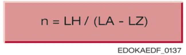
Guide rail length L3
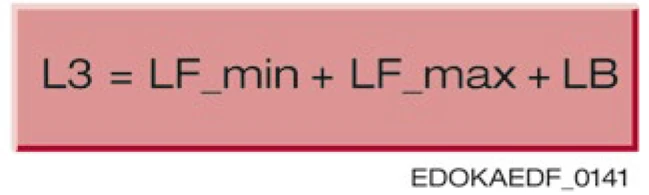
For detailed dimension data, please refer to the complete product catalog.
4.14.4 Sealing Application
The following chart provides an overview of different seal types, their characteristics, and applicable application areas.
| Operating conditions | Without end wipers | Low-friction wiper¹ | Standard wiper | Additional wiper (NBR) | Additional wiper (Viton) | Metal wiper | Bellows |
|---|---|---|---|---|---|---|---|
| Order code | QO (BM only) | QL (BM only) | QN | ZCN (MR) / ZBN (BM) | ZCV (MR) / ZBV (BM) | ASM (MR) / ABM (BM) | FBB (BM) / FBM (MR 25-65) |
| Cleanroom | • | ||||||
| Minimal contamination | • | • | |||||
| Normal contamination | • | ||||||
| Heavy contamination | • | • | |||||
| Dust | (•) | • | • | • | |||
| Coarse, hot swarf | • | ||||||
| Splashes of water | (•) | • | • | • | |||
| Chemicals, coolant | • | ||||||
| Minimal push forces | • | • | • |
• = suitable (•) = suitable under certain conditions ¹ not available for MONORAIL MR
Sealing System Visual Comparison
Without End Wipers (Q0)
Cleanroom applications, lowest thrust
Low-Friction Wiper (QL)
Low contamination environments, low thrust
Standard Wiper (QN)
General industrial applications
NBR Additional Wiper
High contamination and coolant environments
Viton Additional Wiper
High temperature and chemical corrosion environments
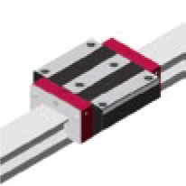
Metal Wiper
Extreme contamination environments
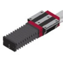
Sealing System Performance Comparison Chart