Drawing
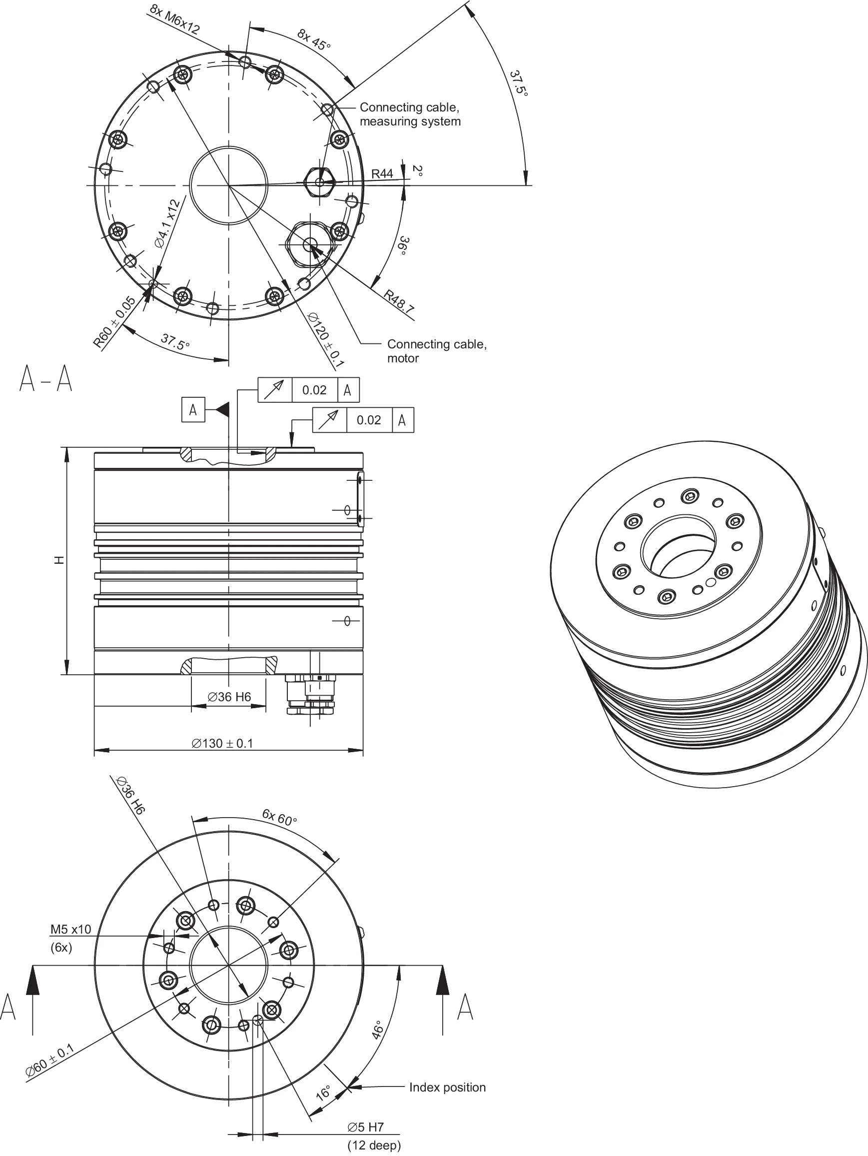
RDDS1-130x110-S-B-CA dimensional drawing — showing top view, section A-A, bottom view, and 3D view; annotations include 8xM6x12 tapped holes, 8x45°/6x60° hole distribution, R48.7/R44/R60 radii, Ø5H7 (12 mm deep) locating holes, M5x10 (6x) tapped holes, Ø36 H6 inner diameter, and cable outlets for measuring system and motor
System Data
Note on Values
Tolerance range for values: ±5%, unless otherwise stated. On housing of the rotary system the maximum temperature of 60 °C must not be exceeded by default.
| RDDS1-130xH | Symbol | Unit | RDDS1-130x110 | RDDS1-130x135 | RDDS1-130x160 | RDDS1-130x185 |
|---|---|---|---|---|---|---|
| Diameter x height | DxH | mm | 130x110 | 130x135 | 130x160 | 130x185 |
| Inner diameter: stage plate | dsp | mm | 36 | 36 | 36 | 36 |
| Inner diameter: base plate | dbp | mm | 36 | 36 | 36 | 36 |
| Measuring system 1 Vpp — resolution (inc) | ||||||
| Option 1 | — | inc | 3600 | 3600 | 3600 | 3600 |
| Option 2 | — | inc | 9000 | 9000 | 9000 | 9000 |
| Option 3 | — | inc | 18000 | 18000 | 18000 | 18000 |
| Limiting speed of bearing | nlim | rpm | 475 | 475 | 475 | 475 |
| Mass | m | kg | 7.0 | 9.6 | 12.2 | 14.8 |
| Moment of inertia | J | kgm² | 0.0013 | 0.0016 | 0.0019 | 0.0022 |
| Axial/radial runout | SR/KR | µm | ±10 | ±10 | ±10 | ±10 |
| Absolute accuracy | Δφabs | arcsec | ≤30 | ≤30 | ≤30 | ≤30 |
| Repeatability | Δφrep | arcsec | ≤5 | ≤5 | ≤5 | ≤5 |
| Axial load | Fax | N | 358.0 | 358.0 | 358.0 | 358.0 |
| Radial load | Frad | N | 45.0 | 45.0 | 45.0 | 45.0 |
| Moment impact (tilting torque) | Ttilt | Nm | 8.8 | 8.8 | 8.8 | 8.8 |
Note: Tolerance range for values: ±5%. On housing of the rotary system the maximum temperature of 60 °C must not be exceeded by default. Subject to modification without previous notice.
Motor Specifications — Independent of Winding
Note on Values
Tolerance range for values: ±5%; ripple torque and power loss: ±10%. The stated motor data relate to a fixing of the rotary system on a mounting plate with a surface of ca. 73,600 mm².
| Motor specifications | Symbol | Unit | RDDS1-130x110 | RDDS1-130x135 | RDDS1-130x160 | RDDS1-130x185 |
|---|---|---|---|---|---|---|
| Number of pole pairs | P | — | 7 | 7 | 7 | 7 |
| Maximum operating voltage | U | V | 600 | 600 | 600 | 600 |
| Ultimate torque at Iu | Tu | Nm | 10.5 | 21.8 | 32.7 | 43.7 |
| Peak torque (saturation range) at Ip | Tp | Nm | 8.9 | 18.6 | 27.8 | 37.1 |
| Peak torque (linear range) at Ipl | Tpl | Nm | 6.5 | 13.6 | 20.4 | 27.3 |
| Continuous torque - water cooled - at Icw | Tcw | Nm | 6.2 | 12.4 | 18.3 | 24.6 |
| Continuous torque - not cooled - at Ic | Tc | Nm | 2.9 | 5.2 | 7.2 | 9.0 |
| Stall torque - water cooled - at Isw | Tsw | Nm | 4.4 | 8.8 | 12.9 | 17.4 |
| Stall torque - not cooled - at Is | Ts | Nm | 2.1 | 3.7 | 5.1 | 6.4 |
| Ripple torque (cogging) at I = 0 | Tr | Nm | 0.06 | 0.125 | 0.19 | 0.255 |
| Power loss at Tp (statical at 25 °C) | Plp | W | 389 | 590 | 792 | 956 |
| Power loss at Tpl (statical at 25 °C) | Plpl | W | 210 | 319 | 427 | 516 |
| Power loss at Tcw | Plw | W | 253 | 358 | 463 | 568 |
| Power loss at Tc (statical at 25 °C) | Plc | W | 42 | 47 | 53 | 56 |
| Thermical resistance (water cooled) | Rth | K/W | 0.396 | 0.280 | 0.216 | 0.176 |
| Motor constant (at 25 °C) | km | Nm/√W | 0.45 | 0.76 | 0.99 | 1.20 |
| Cooling-water flow-rate | dV/dt | l/min | 0.68 | 1.36 | 2.04 | 2.72 |
| Cooling-water temperature-difference | Δϑ | K | 5.00 | 5.00 | 5.00 | 5.00 |
Note: Tolerance range for values: ±5%; ripple torque and power loss: ±10%. The stated motor data relate to a fixing of the rotary system on a mounting plate with a surface of ca. 73,600 mm². Subject to modification without previous notice.
Winding Specifications
Winding Types
The RDDS1-130xH series is available in the following winding types:
- WL: available for RDDS1-130x110, RDDS1-130x135, RDDS1-130x160, RDDS1-130x185
- WM: available for RDDS1-130x160, RDDS1-130x185
RDDS1-130x110 and RDDS1-130x135 are available with WL winding only. Tolerance range for values: ±5% in general; electrical resistance: ±10%; inductance: ±15%.
| Winding specifications | Symbol | Unit | 130x110 WL | 130x135 WL | 130x160 WL | 130x160 WM | 130x185 WL | 130x185 WM |
|---|---|---|---|---|---|---|---|---|
| Torque constant | kT | Nm/Arms | 0.92 | 1.93 | 2.89 | 1.45 | 3.86 | 1.93 |
| Back EMF constant | ku | Vs/rad | 0.75 | 1.58 | 2.36 | 1.18 | 3.15 | 1.58 |
| Limiting speed — UDCL = 280 V | ||||||||
| at Ip, UDCL = 280 V | nlp | rpm | 2886 | 1321 | 841 | 1844 | 604 | 1355 |
| at Icw, UDCL = 280 V | nlw | rpm | 2900 | 1337 | 858 | 1861 | 618 | 1370 |
| at Ic, UDCL = 280 V | nlc | rpm | 3025 | 1433 | 946 | 1950 | 703 | 1454 |
| Limiting speed — UDCL = 600 V | ||||||||
| at Ip, UDCL = 600 V | nlp | rpm | 5821 | 2727 | 1779 | 3722 | 1307 | 2761 |
| at Icw, UDCL = 600 V | nlw | rpm | 5835 | 2743 | 1796 | 3739 | 1321 | 2776 |
| at Ic, UDCL = 600 V | nlc | rpm | 5960 | 2839 | 1885 | 3827 | 1406 | 2860 |
| Limiting speed for continuous running* | ncr | rpm | 1286 | 1286 | 1286 | 1286 | 1286 | 1286 |
| Electrical resistance, phase to phase (25 °C) | R25 | Ω | 2.8 | 4.25 | 5.7 | 1.425 | 6.88 | 1.72 |
| Inductance, phase to phase | L | mH | 12.9 | 21.5 | 31.65 | 7.9 | 43.7 | 10.925 |
| Ultimate current | Iu | Arms | 14.15 | 14.15 | 14.15 | 28.30 | 14.15 | 28.30 |
| Peak current (saturation range) | Ip | Arms | 11.32 | 11.32 | 11.32 | 22.64 | 11.32 | 22.64 |
| Peak current (linear range) | Ipl | Arms | 7.07 | 7.07 | 7.07 | 14.14 | 7.07 | 14.14 |
| Continuous current at Plw (water cooled) | Icw | Arms | 6.68 | 6.45 | 6.33 | 12.66 | 6.38 | 12.77 |
| Continuous current at Plc (not cooled) | Ic | Arms | 3.15 | 2.72 | 2.50 | 4.99 | 2.33 | 4.66 |
| Stall current at zero speed (water cooled) | Isw | Arms | 4.72 | 4.56 | 4.48 | 8.95 | 4.51 | 9.03 |
| Stall current at zero speed (not cooled) | Is | Arms | 2.23 | 1.92 | 1.77 | 3.53 | 1.65 | 3.30 |
| Maximum winding temperature | ϑ | °C | 110 | 110 | 110 | 110 | 110 | 110 |
| Interrupting sensor temperature | ϑ | °C | 100 | 100 | 100 | 100 | 100 | 100 |
Note: Tolerance range for values: ±5%; electrical resistance: ±10%; inductance: ±15%. *For limiting speed for continuous running (ncr), refer to the Glossary in the catalogue. Subject to modification without previous notice.