17.1 Principles
The load capacities are based on the principles of DIN 636.
In accordance with DIN in most applications a permanent overall deformation of 0.0001 times the rolling element diameter can be permitted without adversely affecting the operating behaviour of the bearing. Consequently, the static load capacity C0 is set sufficiently high that the aforementioned deformation occurs approximately when the equivalent static load corresponds to the static load capacity. Being guided by the dynamic load capacity C is recommended so that the aforementioned overall deformation does not occur.
The dynamic load capacity C is the load at which a nominal service life L of 100 km of travel distance is achieved. It is important to note when calculating the service life that not only the load, which acts vertically on the guideway, should be taken into account but also the load spectrum of all acting forces and moments.
The service life corresponds to the total travel distance in meters which a guideway facilitates. And this is before any noticeable material fatigue on one of the roller guideway elements. The nominal service life is achieved when 90% of the guideways of identical construction reach or exceed the corresponding travel distances under normal operating conditions.
Critical for the dimensioning of the guideways are the loads occurring proportionally with the dynamic load capacity C.
The dynamic load capacity C as given in the catalog corresponds to (≙) the definition of C100.
Definition of service life
As previously mentioned, the dynamic load capacity C100 is based on a service life of 100 km. Other manufacturers frequently indicate the load capacity C50 for a service life of 50 km. The resulting load capacities from this are more than 20% higher than specified by the DIN ISO standard.
Conversion example for ball bearings
Convert C50 load capacities to C100 in accordance with the DIN ISO standard:
C100 = 0.79 · C50
Convert C100 load capacities to C50:
C50 = 1.26 · C100
C50 = dynamic load capacity C in N for 50 km of travel distance
C100 = dynamic load capacity C in N for 100 km of travel distance, defined in accordance with DIN ISO standard
17.2 Calculation of Service Life L in Accordance with the DIN ISO Standard
17.2.1 The Formula for Calculating the Nominal Service Life for Ball Guideways in Meters is as follows:
L = a · (Ceff / P)3 · 105 m
a = Event probability factor
Ceff = Effective load carrying capacity N
P = Dynamic, equivalent load in N
L = Nominal service life in m
Event probability factor a
The load carrying capacities for roller-contact bearings correspond to the DIN ISO standard. This represents a value from the service life calculation, which has a 90% chance of being exceeded during operational use of the guideway.
If the previously mentioned theoretical service life probability factor of 90% is not sufficient, the service life values will need to be adjusted by a factor a.
| Event probability in % | 90 | 95 | 96 | 97 | 98 | 99 |
|---|---|---|---|---|---|---|
| Factor a | 1 | 0.62 | 0.53 | 0.44 | 0.33 | 0.21 |
17.2.2 The Formula for Calculating Nominal Service Life in Hours is as follows:
Lh = L / (2 · s · n · 60) = L / (60 · vm)
L = Nominal service life in m
Lh = Nominal service life in h
s = Stroke length in m
n = Stroke frequency in min-1
vm = Medium travelling speed in m/min
17.2.3 Effective Load Carrying Capacity Ceff
Constructive and external influences can reduce the dynamic load capacity C of MINI-X products in such a way that Ceff must be calculated.
Ceff = fK · C
Ceff = Effective load carrying capacity N
fK = Contact factor
C = Maximum permissible dynamic load carrying capacity in N
Contact factor fk
If multiple carriages are mounted back-to-back with minimal spacing (Lb < L), an even weight distribution will be difficult to achieve due to the manufacturing tolerances of the guideway elements and mounting surfaces. Installation situations such as these can be allowed for with the contact factor fk:
| Number of carriages | 1 | 2 | 3 | 4 | 5 |
|---|---|---|---|---|---|
| Contact factor fk | 1 | 0.81 | 0.72 | 0.66 | 0.62 |
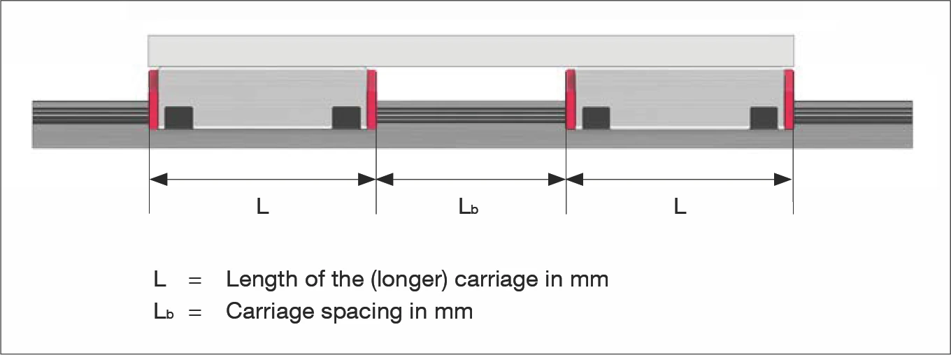
L = Length of the (longer) carriage in mm
Lb = Carriage spacing in mm
17.2.4 Dynamically Equivalent Load P
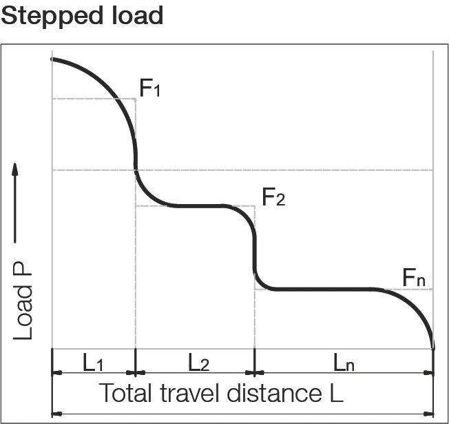
The loads (F) acting on a linear guideway system are subject to frequent fluctuations during operation. This set of circumstances should be taken into account when calculating service life. The varying load absorption of the guideway at varying operating conditions during the travel distance is described as being the dynamic equivalent load P.
P = ³√[(F₁³ · L₁ + F₂³ · L₂ + ... + Fₙ³ · Lₙ) / L]
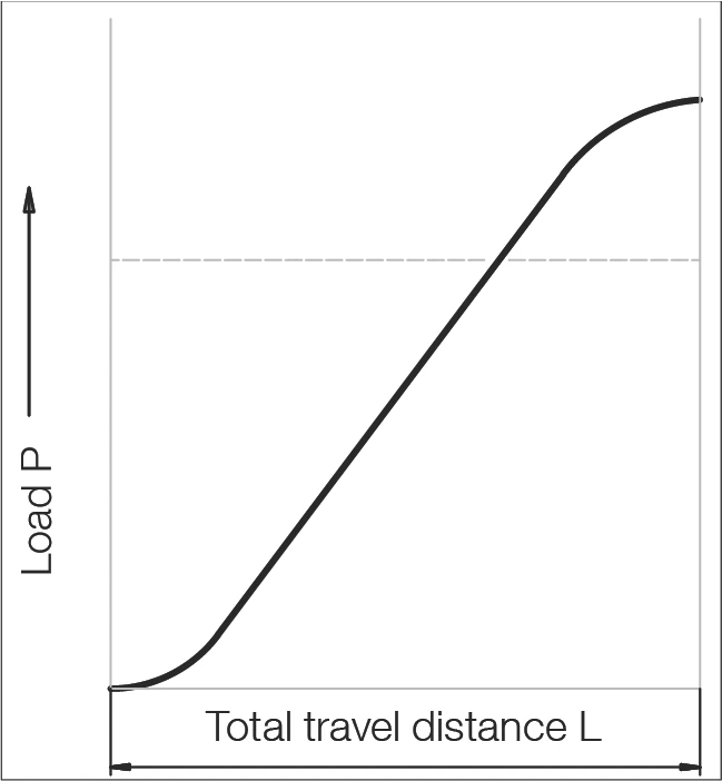
Sinusoidal load
P = 0.7 Fmax
P = Equivalent load in N
F₁ ... Fₙ = Individual load in N during the partial travel distance L₁ ... Lₙ
Fmax = Max. load in N
L = L₁ + ... + Lₙ = Total travel during one load cycle in mm
L₁ ... Lₙ = Partial travel distance in mm of one individual load during a load cycle