Preload and duplex installation techniques are used to enhance rigidity, improve running accuracy, and minimize ball sliding at very high speeds or under high acceleration/deceleration (per the myonic official page Preload and duplex installation).
Why preload is needed (three purposes stated on the official page)
Per the myonic official page Preload and duplex installation:
Increase rigidity
increase rigidity — eliminate clearance and reduce axial and radial elastic displacement.
Improve running accuracy
improve running accuracy — reduce runout and increase rotational accuracy.
Minimize ball sliding at very high speeds or under high acceleration/deceleration
minimize ball sliding at very high speeds or under high acceleration/deceleration
Installation note: myonic duplex bearings are shipped with the correct mounting orientation clearly marked — please follow the markings to ensure the preload direction is correct.
Spring Preload
Spring preload uses stainless steel spring washers between two bearings to apply a constant preload force. This method provides a consistent and adjustable preload effect.
Preload of Paired Bearings
To set the preload of two or more bearings more precisely, the rings must be manufactured as shown. The axial offset of the inner ring face relative to the outer ring face determines the required amount of preload; during installation the axial offset is eliminated and the preload is thereby generated.
X Arrangement (code .9f, face-to-face)
X (face-to-face) duplex installation — the contact lines of the two bearings converge toward the center.
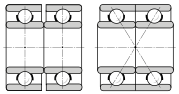
Diagram: X arrangement (face-to-face installation)
X arrangement attributes (per official page)
- More error-tolerant during installation (more error-tolerant with regard to alignment of the bearing system during installation)
- Good rigidity (good rigidity)
For application-specific selection, consult the myonic engineering department; the official page does not list specific application industries.
O Arrangement (code .9d)
O (back-to-back) duplex installation — the contact lines of the two bearings diverge outward.
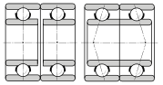
Diagram: O arrangement (back-to-back installation)
O arrangement attributes (per official page)
- Used at high speeds (used at high speeds)
- Increases tilting moment capacity (to increase the tilting moment)
For application-specific selection, consult the myonic engineering department; the official page does not list specific application industries.
Tandem Arrangement (code .9t)
Tandem arrangement mounts two bearings in the same direction, capable of supporting high axial loads in one direction.
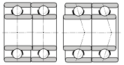
Diagram: Tandem arrangement
Tandem arrangement attributes (per official page)
- Higher axial load capacity in one direction (offers the advantage of a higher axial load capacity in one direction)
- Requires an opposing bearing to absorb axial forces in the opposite direction (requires an opposing bearing to absorb axial forces in the opposite direction)
The official page does not describe radial load capacity or tilting-moment performance for tandem; consult the myonic engineering department for specific selection.