Drawing
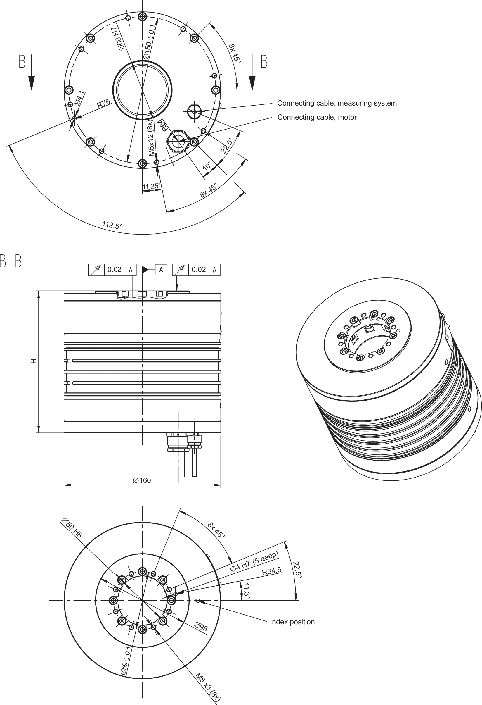
RDDS1-160xH dimensional drawing. Shows outer contour, measuring system connecting cable, motor connecting cable positions and Index position (commutation reference). Height H varies by model (120 / 145 / 170 / 195 mm); stage plate inner diameter dsp = 50 H6, base plate inner diameter dbp = 60 H7.
System Data
Notes
Tolerance range for values: ±5%. On housing of rotary system the maximum temperature of 60 °C must not be exceeded by default.
* In few cases the limiting speed is limited by the winding version of the motor.
Subject to modification without previous notice.
| System Data | Symbol | Unit | RDDS1-160x120 | RDDS1-160x145 | RDDS1-160x170 | RDDS1-160x195 |
|---|---|---|---|---|---|---|
| Diameter × height | D×H | mm | 160×120 | 160×145 | 160×170 | 160×195 |
| Inner diameter: stage plate | dsp | mm | 50 | 50 | 50 | 50 |
| Inner diameter: base plate | dbp | mm | 60 | 60 | 60 | 60 |
| Measuring system 1 Vpp | ||||||
| Incremental lines (inc) | — | inc | 3600 | 3600 | 3600 | 3600 |
| — | inc | 9000 | 9000 | 9000 | 9000 | |
| — | inc | 18000 | 18000 | 18000 | 18000 | |
| Limiting speed of bearing | nlim | rpm | 375 | 375* | 375* | 375* |
| Mass | m | kg | 10.1 | 12.2 | 14.3 | 16.5 |
| Moment of inertia | J | kgm² | 0.0031 | 0.0038 | 0.0045 | 0.0052 |
| Axial/radial runout | SR/KR | µm | ±10 | ±10 | ±10 | ±10 |
| Absolute accuracy | Δφabs | arcsec | ≤30 | ≤30 | ≤30 | ≤30 |
| Repeatability | Δφrep | arcsec | ≤5 | ≤5 | ≤5 | ≤5 |
| Axial load | Fax | N | 500.0 | 500.0 | 500.0 | 500.0 |
| Radial load | Frad | N | 75.0 | 75.0 | 75.0 | 75.0 |
| Moment impact (tilting torque) | Ttilt | Nm | 15.1 | 15.1 | 15.1 | 15.1 |
Motor Specifications – Independent of Winding
Notes
Tolerance range for values: ±5%. Tolerance range for values "ripple torque" and "power loss": ±10%.
The stated motor data relate to a fixing of the rotary system on a mounting plate with a surface of ca. 73,600 mm².
Subject to modification without previous notice.
| Motor Specifications | Symbol | Unit | RDDS1-160x120 | RDDS1-160x145 | RDDS1-160x170 | RDDS1-160x195 |
|---|---|---|---|---|---|---|
| Number of pole pairs | P | — | 11 | 11 | 11 | 11 |
| Maximum operating voltage | U | V | 600 | 600 | 600 | 600 |
| Torque Specifications | ||||||
| Ultimate torque at Iu | Tu | Nm | 32.4 | 64.9 | 97.3 | 130.0 |
| Peak torque (saturation range) at Ip | Tp | Nm | 23.5 | 46.9 | 70.4 | 94.0 |
| Peak torque (linear range) at Ipl | Tpl | Nm | 17.2 | 34.5 | 51.7 | 69.0 |
| Continuous torque – water cooled – at Icw | Tcw | Nm | 12.6 | 29.2 | 46.7 | 64.0 |
| Continuous torque – not cooled – at Ic | Tc | Nm | 5.7 | 11.9 | 16.4 | 21.0 |
| Stall torque – water cooled – at Isw | Tsw | Nm | 8.9 | 20.8 | 33.2 | 46.0 |
| Stall torque – not cooled – at Is | Ts | Nm | 4.0 | 8.4 | 11.6 | 15.0 |
| Ripple torque (cogging) at I = 0 | Tr | Nm | 0.07 | 0.14 | 0.21 | 0.30 |
| Power Loss | ||||||
| Power loss at Tp (statical, 25 °C) | Plp | W | 1140 | 1682 | 2225 | 2768 |
| Power loss at Tpl (statical, 25 °C) | Plpl | W | 445 | 657 | 869 | 1081 |
| Power loss at Tcw (water cooled) | Plw | W | 304 | 609 | 913 | 1218 |
| Power loss at Tc (statical, 25 °C, not cooled) | Plc | W | 55 | 89 | 100 | 111 |
| Thermal & Motor Constant | ||||||
| Thermical resistance (water cooled) | Rth | K/W | 0.329 | 0.164 | 0.110 | 0.082 |
| Motor constant (at 25 °C) | km | Nm/√W | 0.77 | 1.26 | 1.64 | 1.96 |
| Cooling Water | ||||||
| Cooling-water flow-rate | dV/dt | l/min | 0.87 | 1.74 | 2.61 | 3.48 |
| Cooling-water temperature-difference | Δϑ | K | 5.00 | 5.00 | 5.00 | 5.00 |
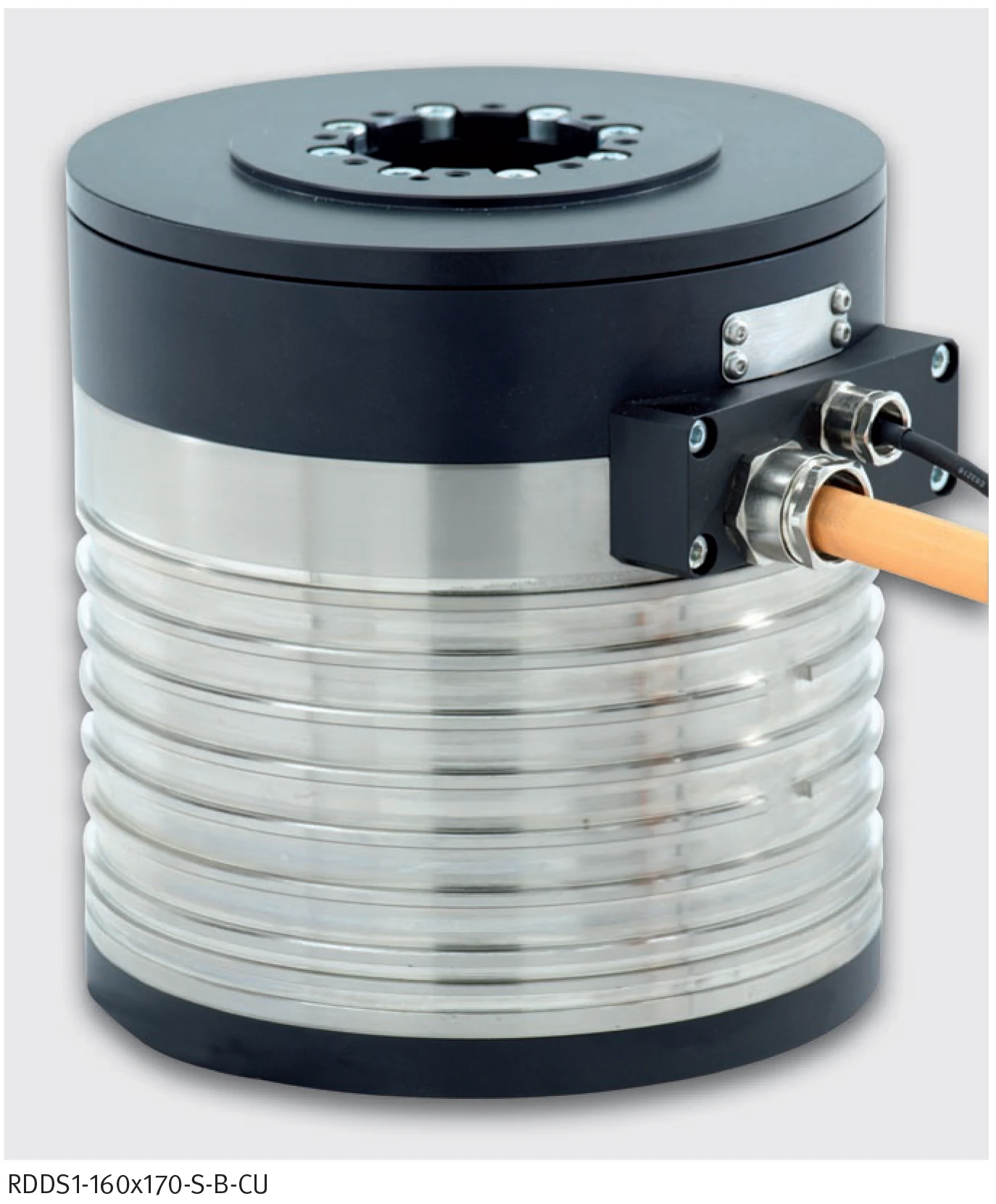
RDDS1-160x170-S-B-CU product view. Shows measuring system and motor connecting cable connector positions.
Winding Specifications — RDDS1-160x120 & RDDS1-160x145
Notes
Tolerance range for values: ±5%. Tolerance range for value "resistance": ±10%. Tolerance range for value "inductance": ±15%.
* See glossary. Subject to modification without previous notice.
Winding versions: WL = Winding low dynamic, WM = Winding medium dynamic, WH = Winding high dynamic.
| Winding Specifications | Symbol | Unit | 160x120 WL | 160x120 WM | 160x120 WH | 160x145 WL | 160x145 WM | 160x145 WH |
|---|---|---|---|---|---|---|---|---|
| Torque constant | kT | Nm/Arms | 2.43 | 1.22 | 0.61 | 4.86 | 2.43 | 1.22 |
| Back EMF constant | ku | Vs/rad | 1.99 | 0.99 | 0.50 | 3.98 | 1.99 | 0.99 |
| Limiting Speed at UDCL = 280 V | ||||||||
| at Ip | nlp | rpm | 508 | 1138 | 2380 | 219 | 541 | 1165 |
| at Icw | nlw | rpm | 885 | 1881 | 3875 | 380 | 847 | 1779 |
| at Ic | nlc | rpm | 1141 | 2354 | 4780 | 549 | 1152 | 2359 |
| Limiting Speed at UDCL = 600 V | ||||||||
| at Ip | nlp | rpm | 1230 | 2564 | 5224 | 588 | 1258 | 2589 |
| at Icw | nlw | rpm | 2028 | 4164 | 8447 | 916 | 1914 | 3916 |
| at Ic | nlc | rpm | 2600 | 5260 | 10583 | 1276 | 2599 | 5246 |
| Limiting speed for continuous running* | ncr | rpm | 818 | 818 | 818 | 818 | 818 | 818 |
| Electrical Properties | ||||||||
| Electrical resistance, phase to phase (25 °C) | R25 | Ω | 5.9 | 1.5 | 0.4 | 8.6 | 2.2 | 0.5 |
| Inductance, phase to phase | L | mH | 24.0 | 6.0 | 1.5 | 47.9 | 12.0 | 3.0 |
| Current Specifications | ||||||||
| Ultimate current | Iu | Arms | 19.1 | 38.1 | 76.2 | 19.1 | 38.1 | 76.2 |
| Peak current (saturation range) | Ip | Arms | 11.3 | 22.7 | 45.4 | 11.3 | 22.7 | 45.4 |
| Peak current (linear range) | Ipl | Arms | 7.1 | 14.2 | 28.4 | 7.1 | 14.2 | 28.4 |
| Continuous current at Plw (water cooled) | Icw | Arms | 5.2 | 10.3 | 20.6 | 6.0 | 12.0 | 23.9 |
| Continuous current at Plc (not cooled) | Ic | Arms | 2.3 | 4.7 | 9.3 | 2.4 | 4.9 | 9.7 |
| Stall current at zero speed (water cooled) | Isw | Arms | 3.7 | 7.3 | 14.6 | 4.3 | 8.5 | 17.0 |
| Stall current at zero speed (not cooled) | Is | Arms | 1.7 | 3.3 | 6.6 | 1.7 | 3.5 | 6.9 |
| Thermal Protection | ||||||||
| Maximum winding temperature | ϑ | °C | 130 | 130 | 130 | 130 | 130 | 130 |
| Interrupting sensor temperature | ϑ | °C | 100 | 100 | 100 | 100 | 100 | 100 |
Winding Specifications — RDDS1-160x170 & RDDS1-160x195
Notes
Tolerance range for values: ±5%. Tolerance range for value "resistance": ±10%. Tolerance range for value "inductance": ±15%.
* See glossary. Subject to modification without previous notice.
| Winding Specifications | Symbol | Unit | 160x170 WL | 160x170 WM | 160x170 WH | 160x195 WL | 160x195 WM | 160x195 WH |
|---|---|---|---|---|---|---|---|---|
| Torque constant | kT | Nm/Arms | 7.30 | 3.65 | 1.82 | 9.73 | 4.86 | 2.43 |
| Back EMF constant | ku | Vs/rad | 5.97 | 2.98 | 1.49 | 7.96 | 3.98 | 1.99 |
| Limiting Speed at UDCL = 280 V | ||||||||
| at Ip | nlp | rpm | 119 | 341 | 760 | 65 | 239 | 556 |
| at Icw | nlw | rpm | 222 | 526 | 1130 | 145 | 372 | 817 |
| at Ic | nlc | rpm | 361 | 768 | 1580 | 266 | 573 | 1186 |
| Limiting Speed at UDCL = 600 V | ||||||||
| at Ip | nlp | rpm | 372 | 822 | 1710 | 263 | 603 | 1271 |
| at Icw | nlw | rpm | 571 | 1217 | 2510 | 405 | 881 | 1835 |
| at Ic | nlc | rpm | 845 | 1730 | 3501 | 630 | 1296 | 2629 |
| Limiting speed for continuous running* | ncr | rpm | 818 | 818 | 818 | 0 | 818 | 818 |
| Electrical Properties | ||||||||
| Electrical resistance, phase to phase (25 °C) | R25 | Ω | 11.4 | 2.9 | 0.7 | 14.2 | 3.6 | 0.9 |
| Inductance, phase to phase | L | mH | 71.9 | 18.0 | 4.5 | 95.9 | 24.0 | 6.0 |
| Current Specifications | ||||||||
| Ultimate current | Iu | Arms | 19.1 | 38.1 | 76.2 | 19.1 | 38.1 | 76.2 |
| Peak current (saturation range) | Ip | Arms | 11.3 | 22.7 | 45.4 | 11.3 | 22.7 | 45.4 |
| Peak current (linear range) | Ipl | Arms | 7.1 | 14.2 | 28.4 | 7.1 | 14.2 | 28.4 |
| Continuous current at Plw (water cooled) | Icw | Arms | 6.4 | 12.8 | 25.5 | 6.6 | 13.3 | 26.4 |
| Continuous current at Plc (not cooled) | Ic | Arms | 2.2 | 4.5 | 9.0 | 2.1 | 4.2 | 8.5 |
| Stall current at zero speed (water cooled) | Isw | Arms | 4.5 | 9.1 | 18.1 | 4.7 | 9.4 | 18.7 |
| Stall current at zero speed (not cooled) | Is | Arms | 1.6 | 3.2 | 6.4 | 1.5 | 3.0 | 6.0 |
| Thermal Protection | ||||||||
| Maximum winding temperature | ϑ | °C | 130 | 130 | 130 | 130 | 130 | 130 |
| Interrupting sensor temperature | ϑ | °C | 100 | 100 | 100 | 100 | 100 | 100 |