15.4 Geometric and Position Accuracy of the Base Surfaces
15.4.1 Permissible Lateral Deviation E1 for MINIRAIL and MINISCALE PLUS
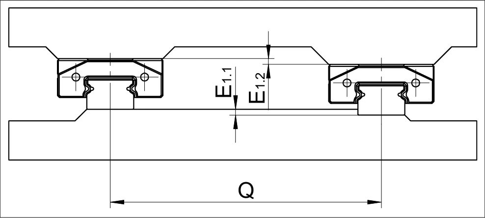
Calculating height deviation E1
Calculating height deviation E₁
E₁ = Q · Vvsp
| E₁ | = | height deviation E1.1 + E1.2 in mm |
| Q | = | guide rail spacing in mm |
| Vvsp | = | preload factor (see following table) |
Preload factor Vvsp
| Dimension of the carriages | Preload class V0 | Preload class V1 |
|---|---|---|
| 7, 9, 12, 15 | 0.00025 Q | 0.00015 Q |
| 14, 18, 24, 42 | 0.00013 Q | 0.00008 Q |
Calculation example for E₁
Spacing Q = 120 mm
0.00015 × 120 mm = 0.018 mm
15.4.2 Permissible Longitudinal Deviation E2 for MINIRAIL and MINISCALE PLUS
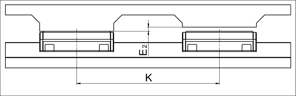
Calculating height deviation E2
Calculating height deviation E₂
E₂ = K · Vvsp
| E₂ | = | height deviation in mm |
| K | = | carriage spacing in mm |
| Vvsp | = | preload factor (see following table, by carriage type) |
Preload factor Vvsp (by carriage type)
| Carriage dimensions | Carriage type | Preload factor Vvsp |
|---|---|---|
| 7, 9, 12, 15 | MNNS (short) | 0.00010 K |
| 7, 9, 12, 15 | MNN (standard) | 0.00005 K |
| 14, 18, 24, 42 | MNN (standard) | 0.00004 K |
| 7, 9, 12, 15 | MNNL (long) | 0.00004 K |
| 14, 18, 24, 42 | MNNL (long) | 0.00003 K |
| 7, 9, 12, 15 | MNNXL (extra long) | 0.00003 K |
Calculation example for E₂
Spacing K = 700 mm
0.00003 × 700 mm = 0.021 mm
15.4.3 Flatness E6 and E7 of the Mounting Surfaces
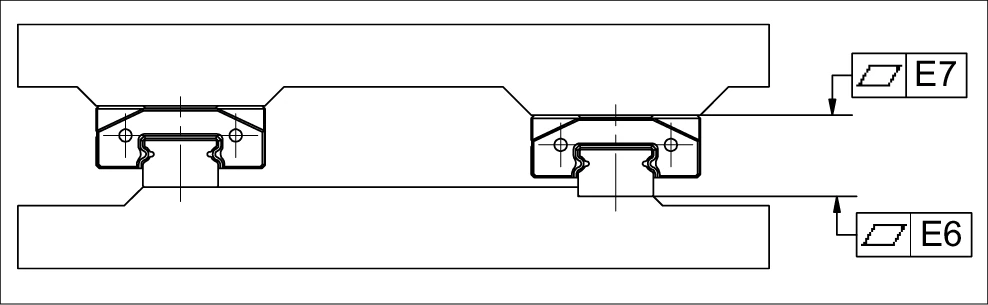
Mounting surface flatness measurement diagram
For the flatness E6 of the guideway surface over the entire length, we recommend the running accuracy values for the corresponding accuracy class described in chapter 7.2.4.
For the flatness E7 of the carriage surface, target the values in the following table.
MINIRAIL and MINISCALE PLUS
| Size | Flatness (μm) |
|---|---|
| 7 | 3 |
| 9 | |
| 12 | 4 |
| 15 | |
| 14 | |
| 18 | |
| 24 | 5 |
| 42 |
MINISLIDE MS and MSQ
For the flatness E7 of the carriage surface, target the values in the following table.
| Size | Flatness (μm) |
|---|---|
| 4 | 2 |
| 5 | |
| 7 | 3 |
| 9 | |
| 12 | 4 |
| 15 |
15.4.4 Parallelism Tolerance of the Reference Surfaces for MINIRAIL and MINISCALE PLUS
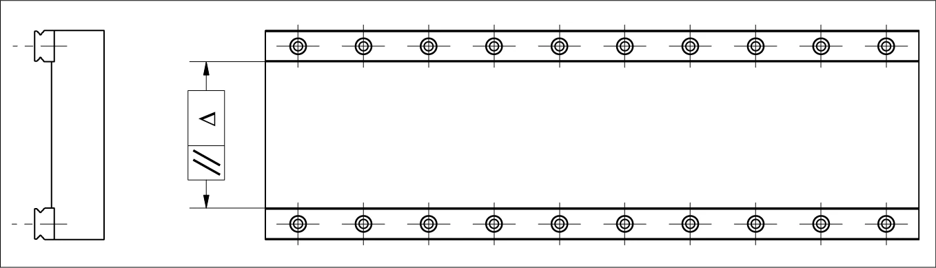
Reference surface parallelism tolerance measurement diagram
Guideways which are not parallel-aligned generate unplanned loads over the stroke length of the guideway system, subjecting the tracks to additional stresses. This reduces the running accuracy of the guideway and can shorten service life. The following parallelism tolerances Δ must therefore be observed.
| Preload class | Rail width (mm) | |||
|---|---|---|---|---|
| 7 and 14 | 9 and 18 | 12 and 24 | 15 and 42 | |
| V0 | Δ 0.003 mm | Δ 0.005 mm | Δ 0.008 mm | Δ 0.010 mm |
| V1 | Δ 0.002 mm | Δ 0.003 mm | Δ 0.004 mm | Δ 0.005 mm |
Important: Parallelism tolerance is critical to ensuring the long-term performance and accuracy of the guideway system. Verification with appropriate measuring tools should be carried out during installation.