Accurately calculating the forces and torques acting on the bearing position is the prerequisite for selecting the optimum bearing size and guaranteeing the required service life. The following is based on the official myonic technical manual.
1. Calculation of Loads
All acting forces must be taken into account, including:
- Weight of the moving part
- Centrifugal force (imbalance)
- Dynamic loads (acceleration / deceleration)
- Forces generated by belt or gear drives
- Preload Fap of duplex bearings
1.1 Pure Radial Load
When the external force acts perpendicular to the shaft axis:
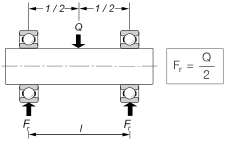
Load Distribution Case 1
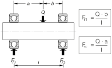
Load Distribution Case 2
Radial Load Formula:
Fr = Qr / 2
(Assuming the load is centered between the two bearings)
1.2 Pure Axial Load
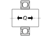
Fa = Q (alternating load)
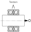
Fa = Q (unidirectional load)

Fa = Q (alternating load)

Fa = Q (alternating load)
Note: To allow an axial load to be supported by several ball bearings, the bearings must be arranged in pairs1 (ring to ring, in direct contact), or precisely manufactured intermediate rings must be used.
1.3 Combined Loads
When the external force Q acts at an angle β, it must be resolved into a radial component (Qr) and an axial component (Qa).
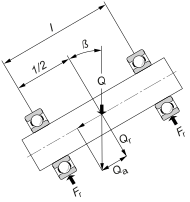
| Load Component | Resolution Formula | Normal installation | Duplex in tandem |
|---|---|---|---|
| Radial Component Qr | Qr = Q · cos β | Fr = Qr / 2 | Fr = Qr |
| Axial Component Qa | Qa = Q · sin β | Fa = Qa (borne by a single bearing) | Fa = Qa |
1.4 Duplex Bearing Preload (Preload Fap)
Ball bearings used in duplex form (O or X arrangement) have a preload Fap, whose value may be greater or smaller than the actual axial load Fa. The magnitude of the preload is adjusted according to the operating conditions and expected service life.
2. Equivalent Dynamic Load (P)
Used to calculate the rated service life (L10) of the bearing. The equivalent load P converts the actual radial and axial loads into a single hypothetical load that has the same effect on bearing life.
Calculation Formulas
| Bearing Type | Formula (P) |
|---|---|
| Radial Deep Groove Ball Bearings | P = X · Fr + Y · Fa |
| Axial Deep Groove Ball Bearings | P = Fa |
About Coefficients X and Y (per the official myonic X/Y lookup table):
These coefficients are determined by Fa / Fr and a second lookup parameter, Fa / (Z · Dw2) (Z = total number of balls, Dw = ball diameter in mm). Refer to the official myonic X/Y coefficient table on the "Service Life Calculation" page for specific values.
3. Equivalent Static Load (P0)
Used to verify the load capacity of the bearing at standstill or at very low speeds, ensuring that no permanent deformation occurs.
Calculation Formulas
| Bearing Type | Formula (P0) | Coefficient Values |
|---|---|---|
| Radial Deep Groove Ball Bearings | P0
= X0 · Fr + Y0 · Fa If P0 < Fr, then P0 = Fr |
X0 = 0.6 Y0 = 0.5 |
| Axial Deep Groove Ball Bearings | P0 = Fa | - |
4. Static Load Safety Factor (S0)
The static safety factor S0 represents the ratio of the basic static load rating C0 to the equivalent static load P0, and is used to evaluate the safety margin.
Calculation Formula:
S0 = C0 / P0
Or, to determine the required C0: C0 = S0 · P0
S0 Guideline Values
| Operating Conditions | S0 Range |
|---|---|
| Low Requirements Smooth operation, no vibrations | 0.5 ... 0.7 |
| Normal Requirements Standard operating conditions, no significant vibrations | 1.0 ... 1.2 |
| High Requirements Impact loads, high reliability requirements | 1.5 ... 2.0 |