使用壽命 L 線上計算機
Interactive Service Life Calculator
動態等效負載 P 計算機
Dynamically Equivalent Load Calculator — feeds P into the L calculator above
使用壽命計算公式
The formulas for calculating service life
對於滾柱和滾針 (For rollers and needles)
對於滾珠 (For balls)
a = 事件概率因子 (Event probability factor)
Ceff = 每個滾動元件的有效負載能力 (N)
P = 動態等效負載 (N)
L = 標稱使用壽命 (m)
事件概率因子 a
Event probability factor a
滾柱接觸軸承的負載能力符合 DIN ISO 標準。這代表使用壽命計算中的一個值,在導軌的操作使用期間,有 90% 的概率超過此值。
如果前面提到的理論使用壽命概率因子 90% 不足夠,則需要通過因子 a 調整使用壽命值。
| 事件概率 (%) Event probability in % | 90 | 95 | 96 | 97 | 98 | 99 |
|---|---|---|---|---|---|---|
| 因子 a Factor a | 1 | 0.62 | 0.53 | 0.44 | 0.33 | 0.21 |
有效負載能力 Ceff
Effective load carrying capacity Ceff
外部影響(例如軌道硬度和溫度)可能會降低負載能力 C,這意味著需要計算 Ceff。
Ceff = 每個滾動元件的有效負載能力 (N)
Effective load carrying capacity per rolling element in N
fH = 硬度因子
Hardness factor
fT = 溫度因子
Temperature factor
C = 每個滾動元件的最大允許負載能力 (N)
Max. permissible load carrying capacity per rolling element in N
硬度因子 fH
Hardness factor fH
無摩擦導軌中偏離標準條件(HRC 58-62)的材料可以用因子 fH 記錄:
| 軌道硬度 (HRC) Track hardness in HRC | 20 | 30 | 40 | 50 | 55 | 56 | 57 | 58-62 |
|---|---|---|---|---|---|---|---|---|
| 硬度因子 fH Hardness factor fH | 0.1 | 0.2 | 0.3 | 0.6 | 0.8 | 0.88 | 0.95 | 1 |
溫度因子 fT
Temperature factor fT
增加的溫度會影響操作條件(材料特性),必須使用因子 fT 考慮。
| 導軌溫度 (°C) Temperature of the guideway in °C | 150 | 200 | 250 | 300 |
|---|---|---|---|---|
| 溫度因子 fT Temperature factor fT | 1 | 0.9 | 0.75 | 0.6 |
Ceff 計算範例
Example calculation for Ceff
給定條件:
- 導軌型號 R6
- 硬度 58-62 HRC ⇒ fH = 1
- 溫度 200°C ⇒ fT = 0.9
- 保持器 AA 6 ⇒ C = 530 N(每個滾柱)
動態等效負載 P
Dynamically equivalent load P
作用在線性導軌系統上的負載 (F) 在操作期間會受到頻繁波動。在計算使用壽命時應考慮這種情況。在行程距離期間,不同操作條件下導軌的不同負載吸收被描述為動態等效負載 P。
階梯負載 (Stepped load)
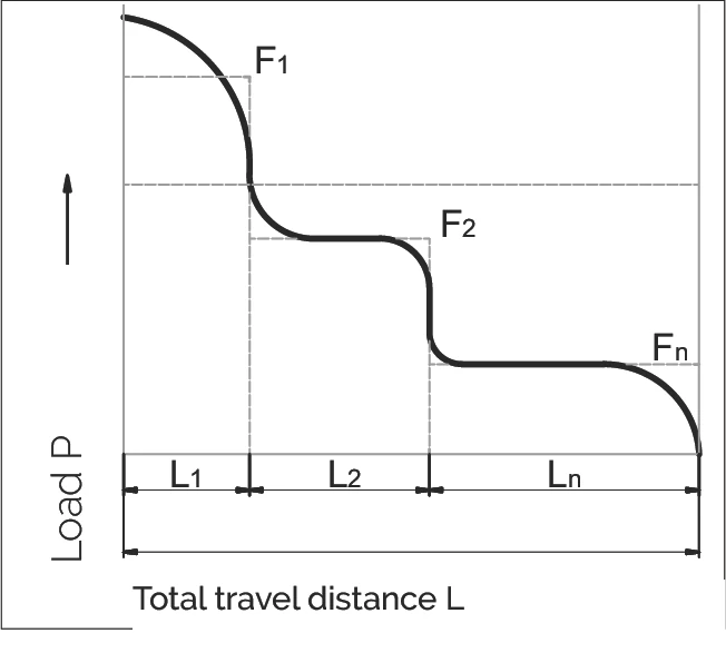
對於滾柱和滾針:
對於滾珠:
正弦負載 (Sinusoidal load)
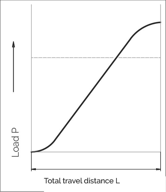
P = 等效負載 (N)
F₁...Fn = 部分行程距離 L₁...Ln 期間的單獨負載 (N)
Fmax = 最大負載 (N)
L = L₁ + ... + Ln = 一個負載循環期間的總行程 (mm)
L₁...Ln = 負載循環期間單獨負載的部分行程距離 (mm)
使用壽命計算範例
Service Life Calculation Example
範例:RNG 6-300 線性導軌配 KBN 6 保持器
Example calculation with a linear guideway of type RNG 6-300 with KBN 6 cage
1. 給定條件 (Given Conditions)
| 事件概率 (Event Probability) | 97%,對應因子 a = 0.44 |
| 滾柱動態負載能力 (Dynamic Load Capacity per Roller) | 1,800 N |
| 滾柱數量 (Number of Rollers) | 16 個 |
| 導軌總負載能力 (Total Guideway Load Capacity) | 16 × 1,800 N = 28,800 N |
| 應用負載 (Applied Load) | P = 10,000 N |
2. 使用壽命計算(以公尺為單位)(Service Life Calculation in Meters)
使用公式:
代入數值:
計算結果:
L = 1,495,412 m
Service life ≈ 1.5 million meters
3. 轉換為使用小時數 (Conversion to Operating Hours)
如果需要以小時為單位表示使用壽命,需要知道以下參數:
- H = 每次行程的距離(公尺)
- t = 完成一次行程所需的時間(秒)
使用壽命(小時)計算公式:
說明:
• 分母中的 3,600 是將秒轉換為小時的換算係數
• Lh 的結果單位為小時 (hours)
• 此公式假設恆定的運動速度和負載條件
修正因子 Rtmin 判定器
R_tmin Determination Helper
修正因子 Rtmin
The correction factor Rtmin
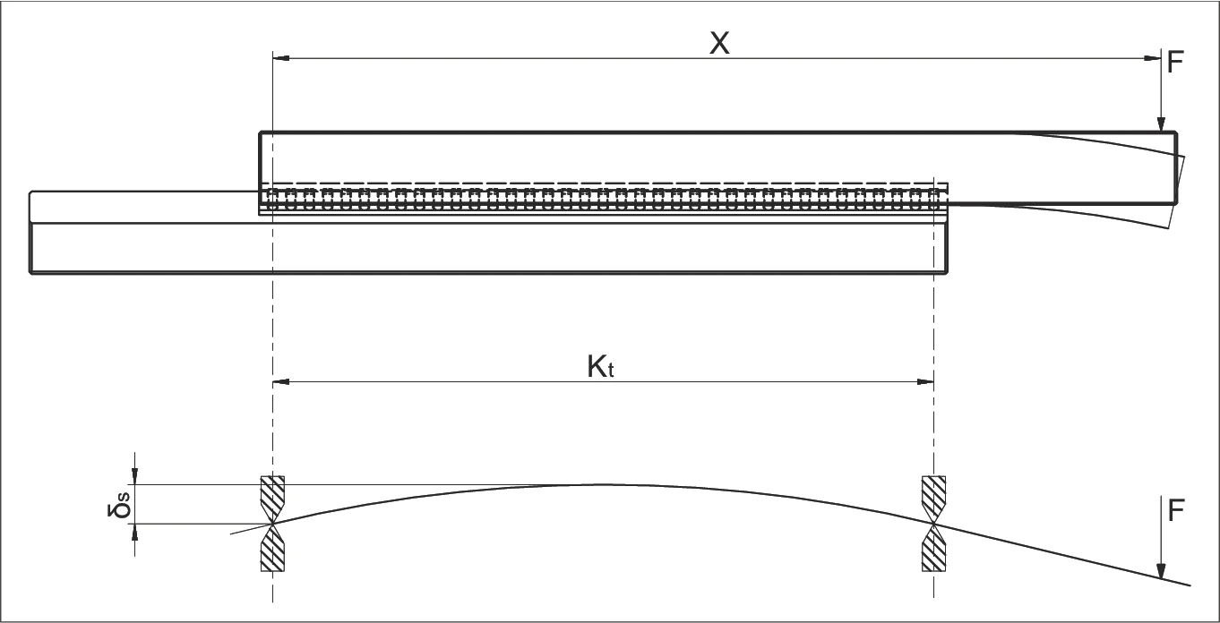
在前面的章節中,我們說明了如何根據給定的負載能力和實際負載來計算使用壽命。在此過程中,必須考慮每個保持器的負載滾動元件數量 (Rt)。
同樣重要的是評估周圍結構在向無摩擦導軌傳遞力時的行為。彈性變形或工具機中的幾何誤差會導致只有一部分安裝的滾動元件能有效地吸收負載。
對於這個與應用相關的問題,通常很難做出可靠的判斷,例如通過對功能模型進行量測或使用基於有限元方法的計算。因此,通常採取簡化措施進行尺寸計算,即使用修正因子 Rtmin 將外部負載分配到較少的滾動元件上。
確定 Rtmin
Determining Rtmin
要確定 Rtmin,首先必須根據歷史經驗評估連接結構的剛性:
A = 剛性結構 (Rigid structure)
B = 正常結構 (Normal structure)
參數說明
Parameter Definitions
| 符號 Symbol | 說明 | Description |
|---|---|---|
| δS | 連接結構的變形量 (µm) | Deformation of the connecting structure in µm |
| δA | 滾動元件包括導軌的變形量 (µm) | Deformation of the rolling element including the guide rail in µm (see chapter 12.5) |
| F | 負載 (N) | Load in N |
| X | X 軸上的槓桿臂距離 (mm) | Lever arm distance on x-axis in mm |
| Kt | 負載保持器的長度 (mm) | Load-bearing cage length in mm |
| Rt | 負載滾動元件的數量 | Number of load-bearing rollers |
| Rtmin | 修正因子 | Correction factor |
Rtmin 計算圖表
Chart for Calculating Rtmin
圖表說明:
- 曲線 A:剛性結構 (Rigid structure)
- 曲線 B:正常結構 (Normal structure)
- 橫軸:X/Kt 比值
- 縱軸:Rt 值(Rt/2、Rt/4 等)
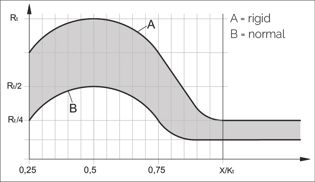
根據圖表計算 Rtmin
To calculate Rtmin according to the diagram applies
| 結構類型 Structure | A(剛性) A (rigid) | B(正常) B (normal) |
|---|---|---|
| X > Kt | Rtmin to Rt/4 | Rtmin |
| X < Kt | 根據圖表 (as per diagram) | 根據圖表 (as per diagram) |
不同滾動元件類型的 Rtmin 值
Rtmin Values for Different Rolling Element Types
| Rtmin | 滾動元件類型 Rolling element type | 保持器型號 Cage types |
|---|---|---|
| 2 | 滾珠 (Balls) | AK |
| 1 | 滾柱 (Rollers) | AA, AC, EE, KBN and KBS |
| 5 | 滾針 (Needles) | SHW and HW |
| 0.5 | 循環單元(滾柱) Recirculating unit with rollers | SR and NRT |
| 1 | 循環單元(滾珠) Recirculating unit with balls | SK, SKD and SKC |
計算範例
Calculation Examples
範例計算 1:線性導軌 R6 配保持器 AK 6/20
Example calculation no. 1: Linear guideway R6 with cage type AK 6/20
給定條件:
- X = 200 mm
- Kt = 171 mm
- 因此使用計算方法:X > Kt
分析:
線性導軌水平排列,因此適用以下條件:
剛性結構的計算 (Calculation for a rigid structure)
- 根據表格,滾珠的滾珠計數 Rtmin to Rt/4 適用
- Rtmin 對應於 2 個滾珠
- Rt/4 對應於 2.50 個滾珠
正常結構的計算 (Calculation for a normal structure)
- 根據表格,Rtmin 適用
- Rtmin 對應於 2 個滾珠
範例計算 2:線性導軌 R6 配保持器 AK 6/11
Example calculation no. 2: Linear guideway R6 with cage type AK 6/11
給定條件:
- X = 75 mm
- Kt = 90 mm
- 因此使用計算方法:X < Kt
剛性結構的計算 (Calculation for a rigid structure)
根據圖表,X = 0.83 of Kt (75 mm : 90 mm),因此 Rt/2
有 11 個負載滾珠,結果為 5.5 個滾珠 (11 個負載滾珠 : 2)
正常結構的計算 (Calculation for a normal structure)
根據圖表 Rt/8
有 11 個負載滾珠,結果為 1.3 個滾珠 (11 : 8)