다양한 응용 분야에는 리니어 가이드 및 순환 유닛의 서로 다른 특성이 필요합니다.
제품 선택 시 다양한 매개변수 및 요소를 고려해야 합니다. 다음에서 이러한 핵심 고려 사항을 상세히 설명합니다.
케이지 길이 K ⇄ 전동체 수 R_A 변환
Cage Length K ⇄ Number of Rolling Elements R_A
스트로크 H와 레일 길이 L 비율 검사기
Stroke / Guideway Length Ratio Checker
스트로크 H와 레일 길이 L의 관계
Relationship between stroke H and length of the guideway L
스트로크 < 400 mm
If the stroke is below 400 mm
스트로크 > 400 mm
If the stroke is above 400 mm
| L | = 리니어 가이드 길이 (mm) Length of the linear guideway in mm |
| H | = 가능 스트로크 (mm) Possible Stroke in mm |
케이지 길이 K 계산
Calculating the cage length K
대칭 스트로크
If the stroke is symmetrical
비대칭 스트로크
If the stroke is asymmetrical
H > H₁ + H₂
H₁₂ = H₁ + H₂
| K | = 케이지 길이 (mm) Cage length in mm |
| L | = 리니어 가이드 길이 (mm) Length of the linear guideway in mm |
| H | = 가능 스트로크 (mm) Possible Stroke in mm |
| H₁ | = 대부분 스트로크 = H/2 (mm) Large partial stroke in mm = H/2 |
| H₂ | = 소부분 스트로크 = H/2 (mm) Small partial stroke in mm = H/2 |
| H₁₂ | = 유효 부분 스트로크 (mm) Effective partial stroke in mm |
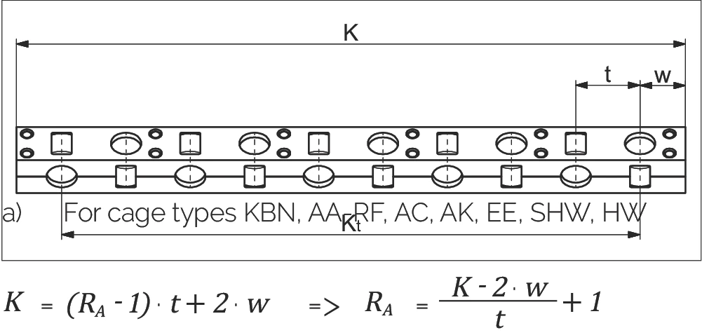
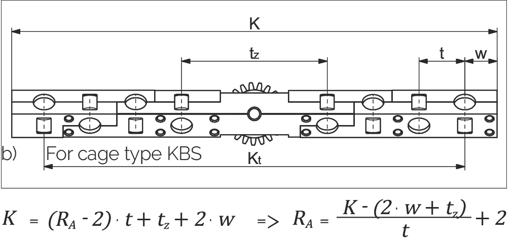
각 케이지의 전동체 수량 (RA) 계산
Calculating the number of rolling elements (RA) per cage
a) 케이지 유형: KBN, AA-RF, AC, AK, EE, SHW, HW
For cage types KBN, AA-RF, AC, AK, EE, SHW, HW
또는
b) 케이지 유형: KBS
For cage type KBS
또는
| K | = 케이지 길이 (mm) Cage length in mm | t | = 케이지 분할 간격 (mm) cage division in mm |
| RA | = 각 케이지의 총 가용 전동체 수 Total available rolling element per cage | Kt | = 부하 지지 길이 (mm) Load-bearing length in mm |
| w | = 케이지 시작점에서 첫 번째 전동체 중심까지의 거리 (mm) Distance from cage start to the middle of the first rolling element in mm | tz | = KBS 케이지 중간 구간의 길이 (mm) Length of the middle section for the KBS cage |
케이지 길이 K와 평균 가이드 레일 간격 Q의 관계
The relationship between the cage length K and the average guideway spacing Q
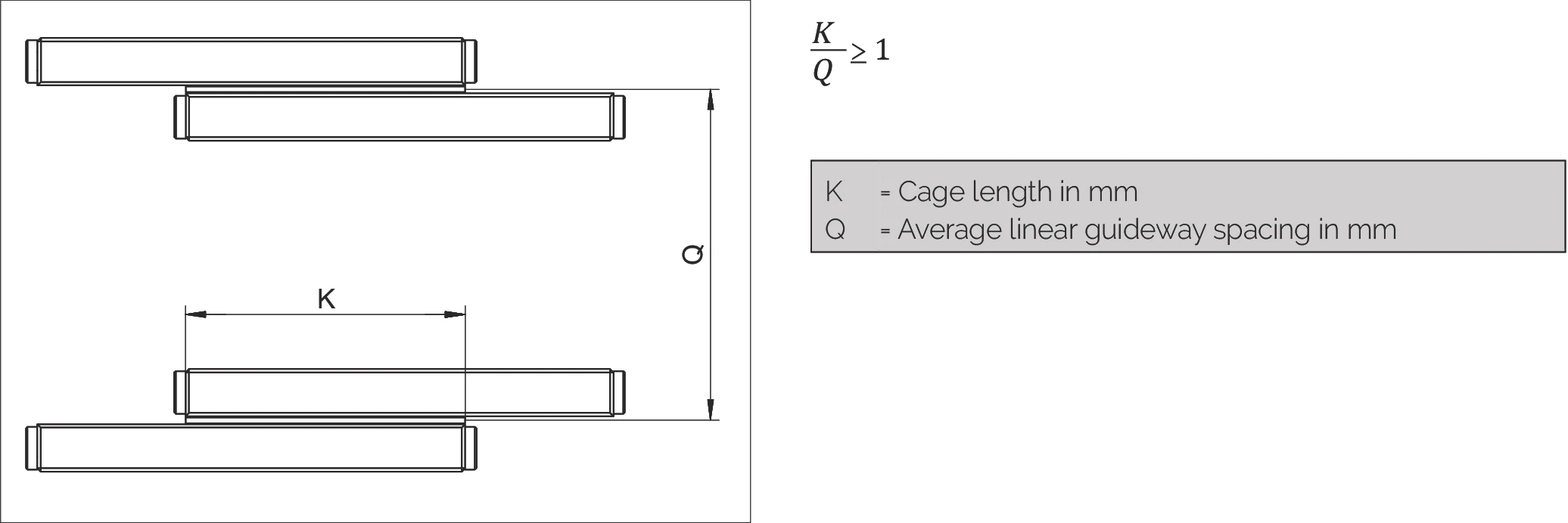
| K | = 케이지 길이 (mm) Cage length in mm |
| Q | = 평균 리니어 가이드 간격 (mm) Average linear guideway spacing in mm |
오버트래블 케이지의 최대 허용 장착 비율
The maximum permissible installation ratio in the case of overrunning cages
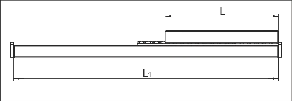
긴 가이드 레일 트랙 위에서 짧은 작업대를 이동해야 할 때, 오버트래블 케이지는 효과적인 솔루션입니다. 이 경우, 가이드 레일의 짧은 트랙에는 반드시 둥근 런인부 (특수 버전 EG, 제7.3장 참조)를 장착하여 오버트래블 케이지로 인한 맥동을 최소화해야 합니다.
최대 허용 장착 비율 L : L₁
Maximum permitted installation ratios L to L₁:
| 고정식 가이드 레일 for fixed guideways | 1 : 2 |
| 적치식 가이드 레일 for laid on guideways | 1 : 4 |
리니어 가이드의 장착 변형
Installation variants for linear guideways
리니어 가이드에는 네 가지 장착 변형이 있습니다. 다양한 리니어 가이드는 엔드피스 형태의 와이퍼 (a₁)*를 사용할 수도 있습니다. 네 가지 경우 모두 다음의 길이 비율이 적용됩니다:
변형 1
- 동일 길이 트랙
- 대칭/비대칭 스트로크
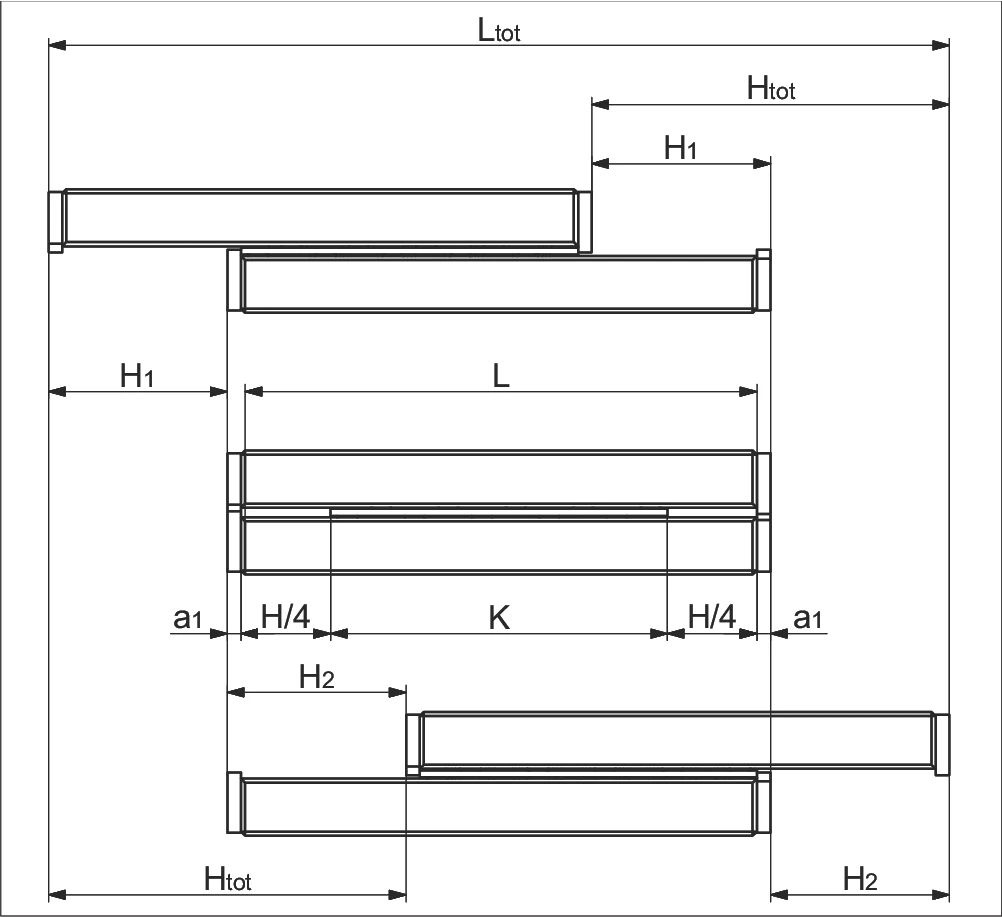
a) 단부 나사, 엔드피스 및 와이퍼 엔드피스 없음
Without end screws, end pieces, and end pieces with wipers
b) 단부 나사, 엔드피스 및 와이퍼 엔드피스 포함**
For end screws, end pieces, and end pieces with wipers**
변형 2
- 동일 길이 트랙
- 단방향 스트로크
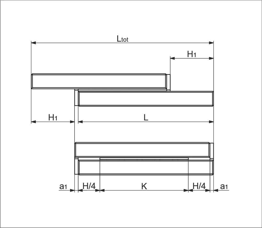
a) 단부 나사, 엔드피스 및 와이퍼 엔드피스 없음
Without end screws, end pieces, and end pieces with wipers
b) 단부 나사, 엔드피스 및 와이퍼 엔드피스 포함**
For end screws, end pieces, and end pieces with wipers**
변형 3
- 비동일 길이 트랙
- 대칭/비대칭 스트로크
- 짧은 트랙 추가
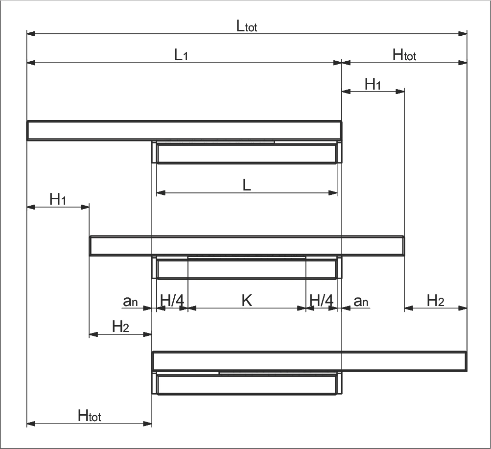
a) 단부 나사, 엔드피스 및 와이퍼 엔드피스 없음
Without end screws, end pieces, and end pieces with wipers
b) 단부 나사, 엔드피스 및 와이퍼 엔드피스 포함**
For end screws, end pieces, and end pieces with wipers**
변형 4
- 비동일 길이 트랙
- 대칭/비대칭 스트로크
- 긴 트랙 추가
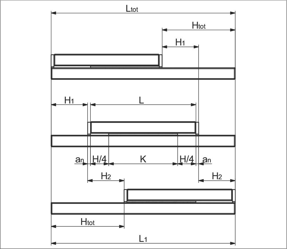
a) 단부 나사, 엔드피스 및 와이퍼 엔드피스 없음
Without end screws, end pieces, and end pieces with wipers
b) 단부 나사, 엔드피스 및 와이퍼 엔드피스 포함**
For end screws, end pieces, and end pieces with wipers**
매개변수 설명
| K | = 케이지 길이 (mm) Cage length in mm | H | = 가능 스트로크 (mm) Possible stroke in mm |
| H₁ | = 대부분 스트로크 = H/2 (mm) Large partial stroke in mm = H/2 | H₂ | = 소부분 스트로크 ≤ H/2 (mm) Small partial stroke in mm ≤ H/2 |
| Htot | = 유효 부분 스트로크 (mm) Effective partial stroke in mm | H12 | = 총 부분 스트로크 = H1 + H2 (mm) Total partial stroke in mm = H1 + H2 |
| L | = 레일 길이 (mm) Length in mm | L₁ | = 긴 트랙 길이 (mm) Length in mm |
| Ltot | = 총 길이 (mm) Total length in mm | an | = 엔드피스 두께 (mm) Thickness of the end piece in mm |
* a₁ 단부 나사, 엔드피스 및 와이퍼 엔드피스, 제5장 참조
** 와이퍼는 리니어 가이드의 운전 특성에 영향을 줄 수 있습니다